Phase-shifting output control circuit and operating method thereof

An output control and phase-shifting technology, applied in the field of phase-shifting output control circuit, can solve problems such as complex structure, easy misconnection, cumbersome wiring, etc.

Inactive Publication Date: 2016-04-27
常州汇邦电子有限公司
View PDF5 Cites 0 Cited by
  • Summary
  • Abstract
  • Description
  • Claims
  • Application Information

AI Technical Summary

Problems solved by technology

[0003] The purpose of the present invention is to provide a phase-shift output control circuit and its working method to solve the technical problems of the traditional phase-shift control circuit with complex circuit structure, cumbersome external wiring and easy misconnection

Method used


Image

  • Phase-shifting output control circuit and operating method thereof
  • Phase-shifting output control circuit and operating method thereof

Examples


Embodiment 1

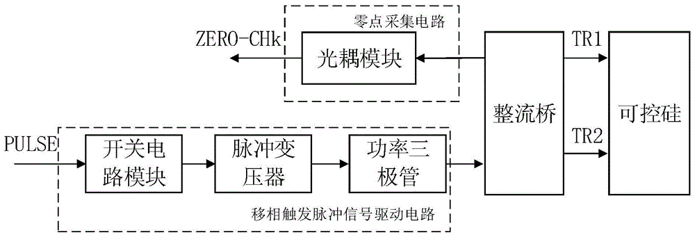
[0021] Such as figure 1 As shown, a phase-shifted output control circuit of the present invention includes: a phase-shifted trigger pulse signal drive circuit, the output end of the phase-shifted trigger pulse signal drive circuit is connected to the common cathode of the rectifier bridge BR1, and the rectifier bridge BR1 is also connected respectively SCR and zero point acquisition circuit.

[0022] When the phase shift trigger pulse PULSE is high, the phase shift trigger pulse signal drive circuit outputs a low level to the common cathode of the rectifier bridge BR1 to trigger the conduction of the thyristor, and the mains voltage across the thyristor is 0V;

[0023] When the phase-shift trigger pulse PULSE is low, the phase-shift trigger pulse signal drive circuit has no output, and the thyristor is cut off, that is, both ends of the thyristor can restore the mains voltage, and when the mains voltage is in the positive half cycle, drive zero point acquisition The circuit obtains...

Embodiment 2

[0035] On the basis of Embodiment 1, Embodiment 2 provides a working method of a phase shift output control circuit.

[0036] The phase shift output control circuit is as described in the first embodiment.

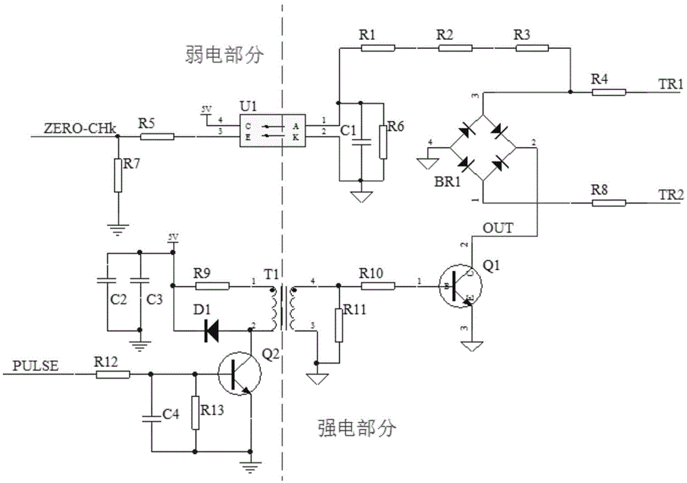
[0037] Such as figure 1 with figure 2 As shown, the working method includes:

[0038] When the phase-shift trigger pulse PULSE is at a high level, the phase-shift trigger pulse signal driving circuit outputs a low level to the common cathode of the rectifier bridge BR1 to trigger the conduction of the thyristor; and

[0039] When the phase-shift trigger pulse PULSE is low, the phase-shift trigger pulse signal drive circuit has no output, and the thyristor is cut off, that is, both ends of the thyristor can restore the mains voltage, and when the mains voltage is in the positive half cycle, drive zero point acquisition The circuit obtains the zero acquisition signal ZERO-CHk.


PUM


Abstract

The invention relates to a phase-shifting output control circuit and an operating method thereof. The phase-shifting output control circuit comprises a phase-shifting trigger pulse signal driving circuit, wherein an output end of the phase-shifting trigger pulse signal driving circuit is connected with a common cathode of a rectifier bridge, and the rectifier bridge is further connected with a silicon controlled rectifier and a zero-point acquisition circuit; when phase-shifting trigger pulse is at high level, the phase-shifting trigger pulse signal driving circuit outputs low level to the common cathode of the rectifier bridge, so as to trigger the silicon controlled rectifier to switch on; and when the phase-shifting trigger pulse is at low level, the phase-shifting trigger pulse signal driving circuit does not output, the silicon controlled rectifier is cut off, both ends of the silicon controlled rectifier restore mains supply voltage, and the zero-point acquisition circuit is driven to obtain a zero-point acquisition signal when the mains supply voltage is at a positive half cycle.

Description

Technical field [0001] The invention relates to the field of phase shift control, in particular to a phase shift output control circuit and a working method thereof. Background technique [0002] The usual phase-shifting chopper output circuit generally adopts transformer pulse to drive the external thyristor output, or MOC3021 thyristor output type photocouple to drive the external thyristor to achieve; the above circuits require additional zero point acquisition circuits, and the output needs to be introduced The power supply of the thyristor collects the zero signal of the same phase as the power supply to make the phase shift circuit work reliably; and when the phase shift output is connected to the wrong wire or the thyristor breaks down, the high voltage of the entire phase shift circuit Part of it is burned; and there is a polarity requirement on the output wiring, if the connection is reversed, the circuit will not work properly. Summary of the invention [0003] The purp...

Claims


Application Information

Patent Timeline
Patent Type & Authority Applications(China)
IPC IPC(8): H03K17/72
CPCH03K17/72
Inventor 周从文陈冲陈步虎左正东
Owner 常州汇邦电子有限公司
Why Eureka
Try Eureka