Remote monitoring system, remote monitoring method, and program

A technology of remote monitoring and main system, applied in hardware monitoring, fault handling not based on redundancy, error detection of redundant data in hardware, etc. Faults and other issues

Active Publication Date: 2016-04-27
NEC FIELDING
View PDF8 Cites 8 Cited by
  • Summary
  • Abstract
  • Description
  • Claims
  • Application Information

AI Technical Summary

Problems solved by technology

[0005] However, in the first method, since a failure cannot be detected from the outside of the information processing device, there is a problem that a failure such as an abnormal stop of the information processing device cannot be detected.
In addition, in the second method, it is necessary to install a fault monitoring device in the customer network, and there is a problem that the installation cost of the fault monitoring device becomes a burden on the customer.

Method used


Image

  • Remote monitoring system, remote monitoring method, and program
  • Remote monitoring system, remote monitoring method, and program
  • Remote monitoring system, remote monitoring method, and program

Examples


no. 1 approach

[0063] (Structure of the first embodiment)

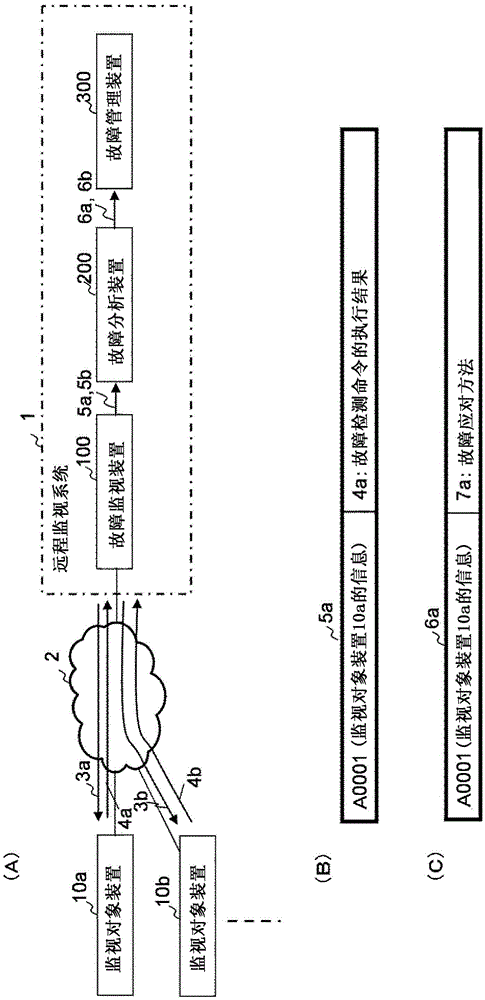
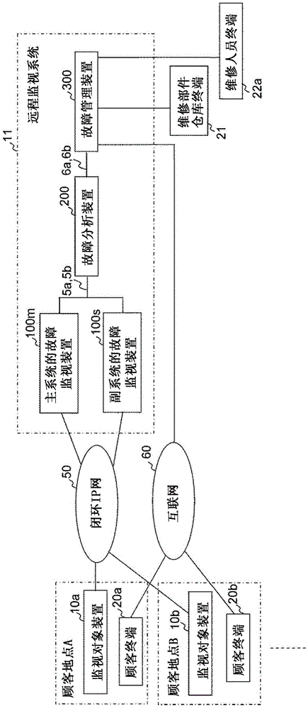
[0064] refer to Figure 3 ~ Figure 6 The configuration of the first embodiment will be described in detail. image 3 It is a block diagram showing the overall configuration of the remote monitoring system 11 of the first embodiment. Such as image 3 As shown, the remote monitoring system 11 remotely monitors the monitoring target devices 10a-b respectively installed at a plurality of customer sites (customer site A, customer site B, etc.) from a monitoring center where the remote monitoring system 11 is installed. Here, the monitoring target devices 10a-b are, for example, information processing devices such as servers, network devices, and PCs (Personal Computers).

[0065] Here, the customer at each customer site does not want to install monitoring equipment in the company's network, and entrusts the company providing the remote monitoring system 11 with maintenance and management of the information processing device in the com...

no. 2 approach

[0134] Next, refer to Figure 23 , Figure 24 A second embodiment will be described. Figure 23 It is a block diagram showing the overall configuration when the remote monitoring system 12 of the second embodiment is applied. In the second embodiment, the functions of the failure analysis device 200 and the failure management device 300 of the first embodiment are operated in one device of the failure analysis management device 400 .

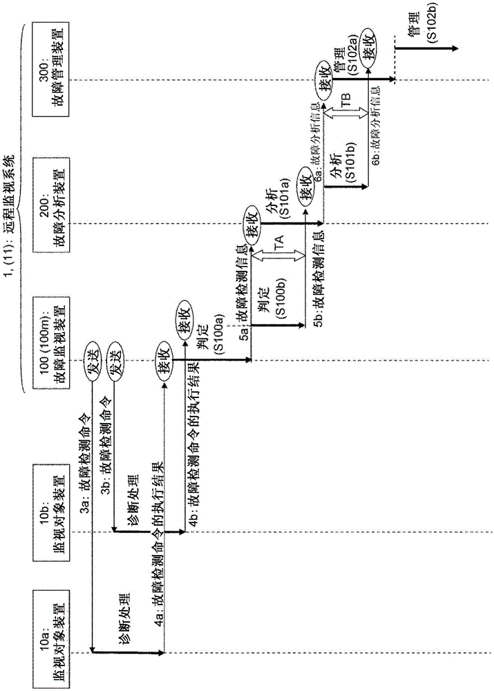
[0135] Figure 24 is a timing chart showing the operation of the second embodiment. exist Figure 24 Among them, each processing content of judgment (S200a), analysis (S201a), management (S202a), judgment (S200b), analysis (S201b) and management (S202b) is related to figure 2 The determination (S100a), analysis (S101a), management (S102a), determination (S100b), analysis (S101b) and management (S102b) are the same. exist Figure 24 In the period TA, the judgment (S200b) by the fault monitoring device 100 and the analysis (S201a) by the f...


PUM


Abstract

Provided is a remote monitoring system having improved processing capability for a plurality of devices to be monitored. A remote monitoring system includes the following fault monitoring device, fault analysis device, and a fault management device. The fault monitoring device transmits a fault detection command to a plurality of devices to be monitored via a network, receives the execution result of the executed fault detection command, determines the presence or absence of a fault, and outputs fault detection information on the device to be monitored that is determined to be faulty. The fault analysis device receives the fault detection information, analyzes the execution result of the fault detection command included in the fault detection information to determine a fault coping method for recovering the fault, and outputs fault analysis information. The fault management device receives the fault analysis information and manages the execution of the fault coping method included in the fault analysis information. Two or more among the fault monitoring device, the fault analysis device, and the fault management device are configured to be able to execute processing in parallel.

Description

[0001] [Remarks about related application] [0002] This invention is based on Japanese patent application: Japanese Patent Application No. 2013-188324 (applied on September 11, 2013), and all the descriptions of the same application are incorporated into this specification by reference. technical field [0003] The present invention relates to a remote monitoring system, a remote monitoring method, and a program. In particular, the present invention relates to a technique for remotely detecting a failure in a device to be monitored via a network. Background technique [0004] Conventionally, the following two methods have been widely used in systems for detecting and maintaining maintenance and management of failures of information processing devices and the like installed at customers. The first method is to introduce a monitoring module into the customer's information processing device, and the monitoring module detects a failure and notifies it. The second method is to...

Claims


Application Information

Patent Timeline
Patent Type & Authority Applications(China)
IPC IPC(8): G06F11/30G06F11/20G06F13/00G06Q50/10
CPCG06F11/0748G06F11/0793G06F11/20G06Q10/20
Inventor 落合晋二
Owner NEC FIELDING
Why Eureka
Try Eureka