Downhole gas-liquid separation device and working method thereof

A technology for a gas-liquid separation device and a working method, which is applied to separation devices, separation methods, chemical instruments and methods, etc., can solve the problems of expensive gas-liquid two-phase motors, without reducing operating costs, increasing operating costs, etc., and achieving a small number of , The effect of avoiding motor damage and improving service life

Active Publication Date: 2016-05-04
JEREH ENERGY SERVICES
View PDF5 Cites 116 Cited by
  • Summary
  • Abstract
  • Description
  • Claims
  • Application Information

AI Technical Summary

Problems solved by technology

In drilling and grinding operations, in order to reduce the operating pressure and improve the discharge of drill cuttings, it is necessary to pump liquid nitrogen, but the gas contained in the liquid will cause great damage to the motor at the bottom, so the current operation site uses a gas-liquid two-phase motor to carry out operation, but the gas-hydraulic two-phase motor is extremely expensive, which increases the operation cost
If the gas-liquid two-phase motor is not used, a gas-liquid separator needs to be installed. The structure of the current gas-liquid separator is relatively complicated and the cost is also relatively expensive, which not only increases the difficulty of maintenance, but also does not reduce the cost of operation.

Method used


Image

  • Downhole gas-liquid separation device and working method thereof
  • Downhole gas-liquid separation device and working method thereof
  • Downhole gas-liquid separation device and working method thereof

Examples


specific Embodiment approach

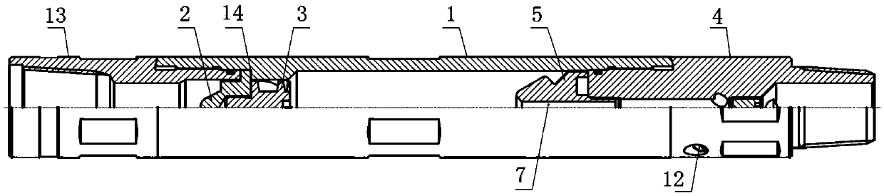
[0031] Such as Figures 1 to 4 As shown, the downhole gas-liquid separation device includes a cylindrical body 1 , and a positioning wheel 2 is fixedly installed in the body 1 .

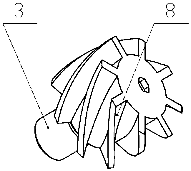
[0032] A rotatable swirl wheel 3 is installed on the positioning wheel 2, the swirl wheel 3 is provided with a spiral wheel piece 8, and the positioning wheel 2 is provided with a fluid channel.

[0033] The main body 1 is connected with a lower joint 4, and the inner end of the lower joint 4 located in the inner cavity of the main body 1 is provided with a shunt joint 5, and the center of the shunt joint 5 is coaxially provided with an air outlet channel 6, and the outer side is provided with a liquid discharge channel 7.

[0034] A space is provided between the swirl wheel 3 and the flow splitter 5, and the inner chamber of this section of the body 1 serves as a working chamber for gas-liquid separation.

[0035] Connect the upper end of the main body 1 to the coiled oil pipe, and connect the lowe...

Embodiment 2

[0038] The structure of embodiment two is basically the same as that of embodiment one, the difference is:

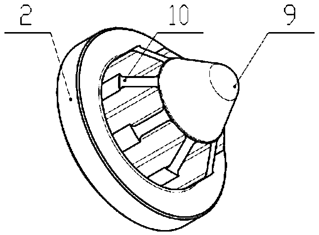
[0039] Such as figure 2 As shown, a protrusion 9 is provided on the outer side of the positioning wheel 2, and the protrusion 9 is in the shape of a truncated cone, and the top is arc-shaped, which is more conducive to spreading the pump liquid. The protrusions 9 are provided with deflectors 10 at intervals, and there are multiple fluid passages, all of which are located between adjacent deflectors 10 .

[0040] When the pump liquid passes through the positioning wheel 2, the protrusion 9 breaks up the pump liquid, and the deflector plate 10 further disperses the pump liquid, and the pump liquid finally enters the corresponding fluid channel through the gap between the deflector plates 10 , and then leave positioning wheel 2.

Embodiment 3

[0042] The structure of embodiment three is basically the same as that of embodiment one, the difference is:

[0043] Such as Figure 4 As shown, the distribution joint 5 is in the shape of a truncated cone, there is a gap between the outer wall of the distribution joint 5 and the inner wall of the body 1 , and an annular flange 11 is provided on the outer wall of the distribution joint 5 .

[0044] Under the action of centrifugal force, the liquid phase in the pump injection fluid flows along the inner wall of the working chamber of the main body 1, then flows into the space between the outer wall of the tap 5 and the inner wall of the main body 1, completely fills the space, and finally passes through The annular flange 11 enters into the drain channel 7 below. The liquid phase of the pump injection liquid is completely filled, and the gap between the outer wall of the shunt joint 5 and the inner wall of the body 1 is sealed. The gas left in the middle under the action of c...


PUM


Abstract

A downhole gas-liquid separation device comprises a barrel-shaped body, and a positioning wheel is fixedly installed in the body. A rotatable swirling wheel is installed on the positioning wheel and provided with spiral wheel blades, and the positioning wheel is provided with fluid channels. A lower connector is connected to the body, a diverting joint is arranged at the inner end, located in an inner cavity of the body, of the lower connector, a gas outlet channel is formed in the center of the diverting joint in a coaxial mode, and the outer side of the diverting joint is provided with liquid drainage channels. An interval is formed between the swirling wheel and the diverting joint. The downhole gas-liquid separation device is small in part number, simple in structure and lower in cost; the swirling wheel is driven to rotate when liquid passes through the swirling wheel to enable the liquid to generate centrifugal force and swirlingly flow in the inner cavity in the mode of being attached to the wall, the liquid in gas is gathered to the center, and then the liquid and the gas flow out through the liquid drainage channels formed in the outer side and the gas outlet channel formed in the center respectively, so that gas and liquid separation is achieved; accordingly, the liquid sent to a motor does not contain the gas, damage to the motor is avoided, and the service life of the motor is prolonged.

Description

technical field [0001] The invention relates to the technical field of downhole operations in oil and gas fields, in particular to a downhole gas-liquid separation device required in downhole operations in oil and gas fields. Background technique [0002] As the staged fracturing reservoir stimulation technology is more and more widely used in unconventional oil and gas reservoir development, the drilling and grinding operations of ball seats and bridge plugs have also increased sharply. In drilling and grinding operations, in order to reduce the operating pressure and improve the reverse discharge of drill cuttings, it is necessary to pump liquid nitrogen, but the gas contained in the liquid will cause great damage to the motor at the bottom, so the current operation site uses a gas-liquid two-phase motor to carry out operation, but the gas-hydraulic two-phase motor is extremely expensive, which increases the operation cost. If the gas-liquid two-phase motor is not used, a...

Claims


Application Information

Patent Timeline
Patent Type & Authority Applications(China)
IPC IPC(8): B01D19/00
CPCB01D19/0052B01D2221/04
Inventor 宁世品叶登胜迟帅
Owner JEREH ENERGY SERVICES
Why Eureka
Try Eureka