
Spraying pressure control system

A pressure control and voltage technology, applied in the direction of spraying devices, can solve the problems of difficult control of paint flow and low spraying efficiency, and achieve the effects of reducing paint waste, improving spraying efficiency, and stable and reliable hardware work

Inactive Publication Date: 2016-05-04
中泰致远(天津)涂料有限公司
View PDF0 Cites 0 Cited by
  • Summary
  • Abstract
  • Description
  • Claims
  • Application Information

AI Technical Summary

Problems solved by technology

[0003] The present invention provides a spraying pressure control system to solve the problems of difficult control of paint flow and low spraying efficiency in the existing spraying system in the above-mentioned background technology

Method used


Image

  • Spraying pressure control system
  • Spraying pressure control system

Examples


Embodiment

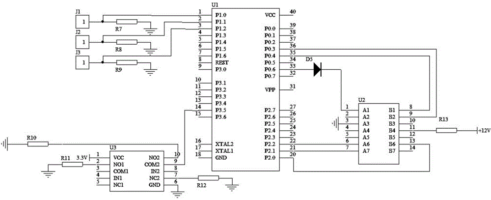
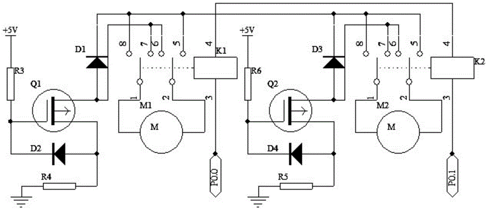
[0017] This embodiment includes: main control circuit ( figure 1 ), the sensor circuit ( figure 1 ),Drive circuit( figure 2 ).

[0018] figure 1 Among them, the main control circuit includes a chip U1, a chip U2, a diode D5, and a resistor R13. The pin 20 of the chip U1 is connected to the pin 13 of the chip U2, its pin 21 is connected to the pin 7 of the chip U2, and its pin 22 is connected to the chip Pin 6 of U2, pin 33 is connected to the anode of diode D5, pin 35 is connected to pin 8 of chip U2, pin 36 is connected to pin 9 of chip U2, pin 1 of chip U2 is connected to the anode of diode D5 The cathode, its pin 3 is grounded, its pin 11 is connected to one end of the resistor R13, and the other end of the resistor R13 is connected to the voltage +12V.

[0019] figure 1 Among them, the sensor circuit includes sensor J1, sensor J2, sensor J3, resistor R7, resistor R8, resistor R9, resistor R10, resistor R11, resistor R12, chip U3, and sensor J1 is connected to pin 1 o...


PUM


Abstract

The invention belongs to the technical field of spraying and particularly relates to a spraying pressure control system. The spraying pressure control system comprises a master control circuit, a sensor circuit and a drive circuit, wherein the master control circuit comprises a chip U1, a chip U2, a diode D5 and a resistor R13, and a pin 20 of the chip U1 is connected with a pin 13 of the chip U2; the sensor circuit comprises a sensor J1, a sensor J2, a sensor J3, a resistor R7, a resistor R8, a resistor R9, a resistor R10, a resistor R11, a resistor R12 and a chip U3, and the sensor J1 is connected with a pin 1 of the chip U1 and one end of the resistor R7; the drive circuit comprises a field-effect transistor Q1, a field-effect transistor Q2, a resistor R3, a resistor R4, a resistor R5, a resistor R6, a diode D1, a diode D2, a diode D3, a diode D4, a feeding motor M1, a discharging motor M2, a switch K1 and a switch K2.

Description

technical field [0001] The invention belongs to the technical field of spraying, in particular to a spraying pressure control system. Background technique [0002] Painting is the main step in coating construction. In order to obtain an ideal coating film, it is necessary to accurately select the coating method according to the properties of the coating, the structure of the workpiece, and the required coating efficiency. The current methods include spraying, electrodeposition coating, automatic deposition coating, dip coating, roller coating and curtain coating, etc. The traditional spraying system is difficult to control the coating flow rate and the spraying efficiency is low. Contents of the invention [0003] The present invention provides a spraying pressure control system to solve the problems of difficult control of paint flow rate and low spraying efficiency in the existing spraying system in the above-mentioned background technology. [0004] The technical prob...

Claims


Application Information

Patent Timeline
Patent Type & Authority Applications(China)
IPC IPC(8): B05B12/00
Inventor 王芙蓉
Owner 中泰致远(天津)涂料有限公司
Learn More