Injection molding die cooling system

A cooling system and injection mold technology, applied in the field of injection molds, can solve the problems of poor cooling effect, reduced yield, difficult water circulation, etc., and achieve the effect of improving the quality of plastic parts, enhancing the circulation ability, and enhancing the cooling effect.

Inactive Publication Date: 2016-05-04
TIANJIN SHANCHUANTE PRECISION MOLD
View PDF0 Cites 4 Cited by
  • Summary
  • Abstract
  • Description
  • Claims
  • Application Information

AI Technical Summary

Problems solved by technology

[0003] Especially in the injection molding process of circular plastic parts, cooling water channels are usually set on the outer edge of the plastic parts. This structure has poor cooling effect, and cooling dead angles often a

Method used


Image

  • Injection molding die cooling system
  • Injection molding die cooling system
  • Injection molding die cooling system

Examples


Example Embodiment

[0017] The present invention will be described in further detail below with reference to the drawings and specific embodiments.

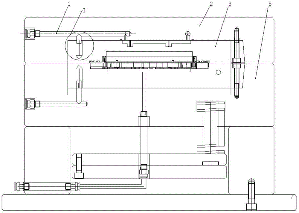
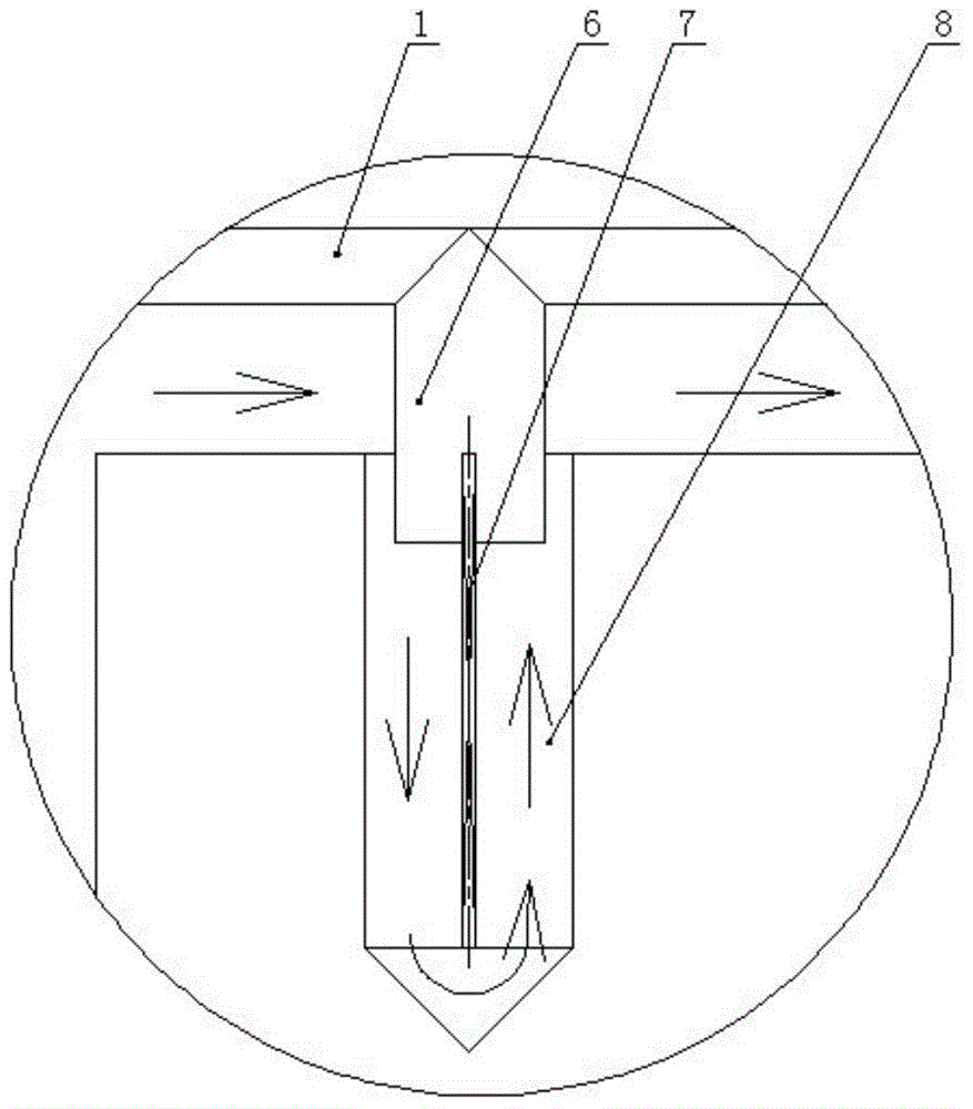
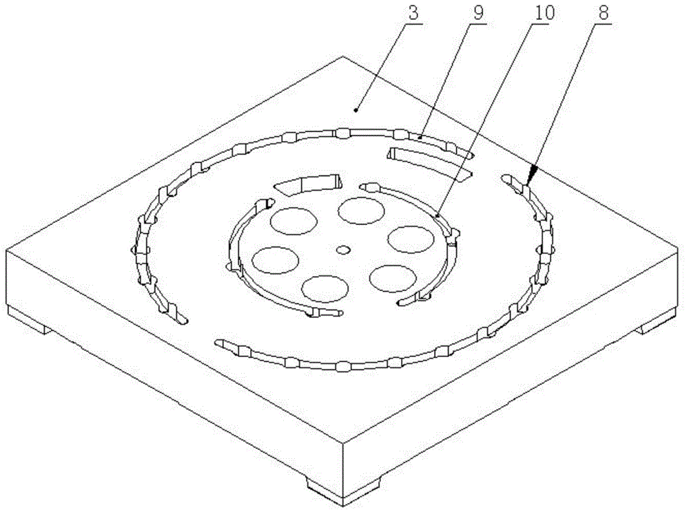
[0018] An injection mold cooling system, such as figure 1 , image 3 As shown, it includes an upper mold 3, a lower mold 5, and a cover plate 2. The upper and lower molds are buckled and installed together, the upper mold is installed with an upper cover, and the upper end of the upper mold is formed with a pair of arc-shaped upper The mold cooling water channel 9 has a plurality of vertical water channels 8 vertically and uniformly formed on the upper mold below the upper mold cooling water channel, a water inlet pipe 1 is formed on the cover plate, and the water outlet 6 of the water inlet pipe corresponds to the vertical water channel.

[0019] The innovation of the present invention lies in:

[0020] 1. A pair of cooling water channels 11 for the lower mold are made on the upper end of the lower mold, such as Figure 4 As shown, the lower mold cooling...


PUM


Abstract

The invention relates to an injection molding die cooling system. The system comprises an upper die, a lower die and a cover plate, the upper die and the lower die are buckled and arranged together, the upper die is provided with an upper cover, the upper end surface of the upper die is provided with a pair of arc-structured upper die cooling water channels, the upper die below the upper die cooling water channels is vertically and uniformly provided with a plurality of vertical water channels, the cover plate is provided with a water inlet tube, the water outlet of the water inlet tube corresponds to the vertical water channels, the upper end surface of the lower die is provided with a pair of lower die cooling water channels, and each of the lower die cooling water channels is a multi-segment bending structure; and the bottom of each of the vertical water channels is a tapered structure, and a spacer is inserted to each of the vertical water channels. The lower die cooling water channels in the system is a multi-segment bending structure; and compared with traditional arc-structured cooling water channels, the cooling water channels in the system have the advantages of large cooling area, enhancement of the cooling effect, and realization of uniform and dead angle-free cooling. The system has the advantages of simple structure, scientific and reasonable design, enhancement of the circulating ability of cooling water, and improvement of the quality of plastic members.

Description

technical field [0001] The invention belongs to the technical field of injection molds, in particular to a cooling system for injection molds. Background technique [0002] The purpose of the injection mold cooling system is to cool the product evenly and eject it into the mold in a short period of time. The quality of the waterway arrangement in the cooling system directly affects the molding and molding cycle of the plastic part. The molding of plastic parts is mainly manifested in the smoothness of the product surface, thermal bending, etc.; in the molding cycle, shortening the cooling time is to improve the molding efficiency. [0003] Especially in the injection molding process of circular plastic parts, cooling water channels are usually arranged on the outer edge of the plastic part. This structure has poor cooling effect, and cooling dead angles often appear, reducing the yield. Some cooling water channels are provided with vertical water channels below. Since the v...

Claims


Application Information

Patent Timeline
IPC IPC(8): B29C45/73
Inventor 金银石
Owner TIANJIN SHANCHUANTE PRECISION MOLD
Why Eureka
Try Eureka