Thick plate printing device

A printing and platen technology, which is applied in printing, printing machines, rotary printing machines, etc., can solve the problems of low printing efficiency and inability to print thick, etc., and achieve the effects of flexible use, improved efficiency, and simple structure

Active Publication Date: 2016-05-04
WUHAN TEXTILE UNIV
View PDF5 Cites 0 Cited by
  • Summary
  • Abstract
  • Description
  • Claims
  • Application Information

AI Technical Summary

Problems solved by technology

[0004] The purpose of the present invention is to overcome the defects and problems in the prior art that cannot print thick fabrics and low printing efficiency, and provide a thick plate printing device that can print thick fabrics and has high printing efficiency

Method used


Image

  • Thick plate printing device
  • Thick plate printing device
  • Thick plate printing device

Examples


Embodiment 1

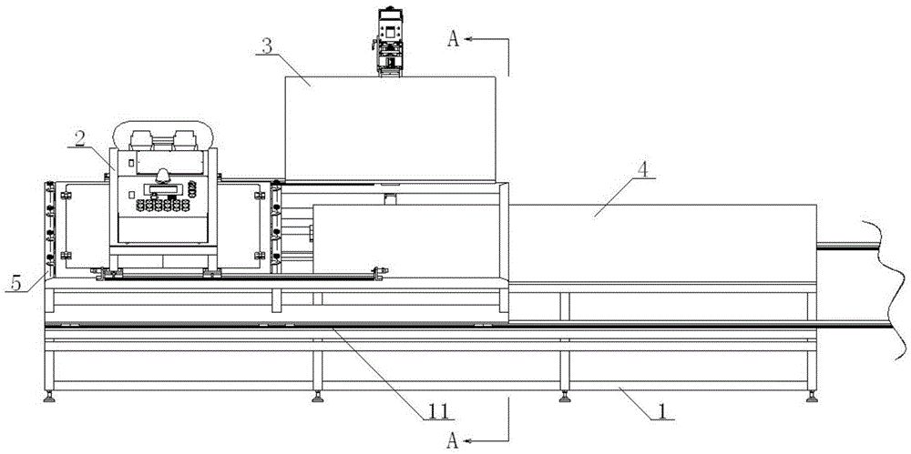
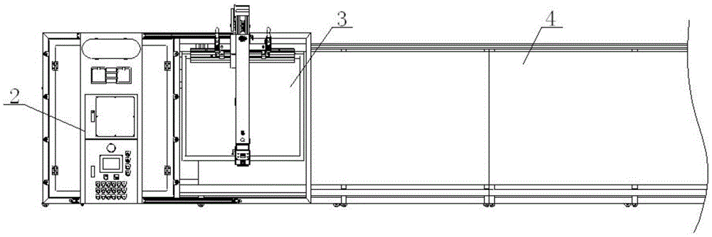
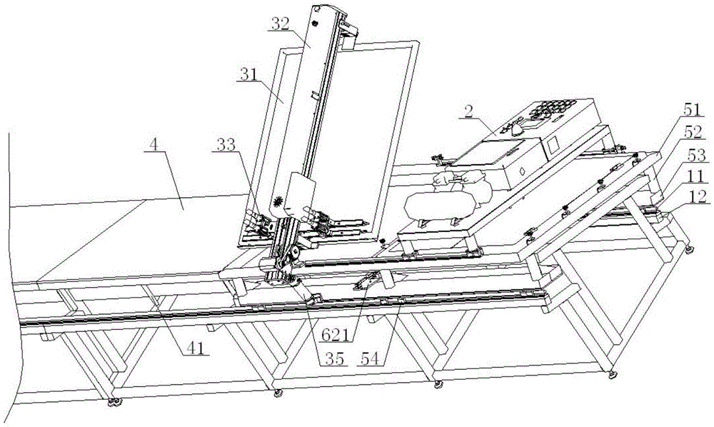
[0046] see Figure 1 to Figure 5 , a thick plate printing device, comprising a frame 1, a heating and drying mechanism 2, and a printing mechanism 3, the front and rear sides of the frame 1 are provided with linear guide rails 11, and the frame 1 is provided with a Platen 4, the position on the left side of platen 4 on the platen 4 is provided with a support mechanism 5, the upper end of the support mechanism 5 is provided with a heating and drying mechanism 2, a printing mechanism 3 in sequence from left to right, and the lower end of the support mechanism 5 is connected to the The linear guide rail 11 is matched, and the printing mechanism 3 includes a screen frame 31 and a printing arm 32. The front part of the printing arm 32 is connected with the front end of the support frame 51 through the printing arm support 34, and the front end of the printing arm 32 is connected by a telescopic cylinder 35. It is connected with the front end of the support plate 53, the lower end o...

Embodiment 2

[0048] Basic content is the same as embodiment 1, the difference is:

[0049] see Figure 1 to Figure 5 , the frame 1 includes a bottom beam 13, a first front vertical beam 14, a first rear vertical beam 15, and a second Front vertical beam 16, the second rear vertical beam 17, the height of the second rear vertical beam 17 is greater than the height of the second front vertical beam 16, the lower end of the second front vertical beam 16 and the second rear vertical beam 17 are all connected with the bottom The upper end surface of the crossbeam 13 is vertically connected, the upper end of the second front vertical beam 16 is connected with the lower end surface of the front part of the platform 4, and the upper end of the second rear vertical beam 17 is connected with the lower end surface of the rear part of the platform 4; The top of the front vertical beam 14 is provided with a front cross beam 110, the front cross beam 110 is perpendicular to the bottom cross beam 13, an...

Embodiment 3

[0051] Basic content is the same as embodiment 1, the difference is:

[0052] see Figure 1 to Figure 5, the support mechanism 5 includes a support frame 51, a support plate 53, and a slider 54. The support frame 51 is located above the platen 4 and the support frame 51 is parallel to the platen 4. The lower end surface of the support frame 51 passes through the pillar 52 It is connected with the upper end surface of the support plate 53, and the lower end surface of the support plate 53 is connected with the upper end surface of the slider 54. The upper end faces are connected;

[0053] The lower end of the front portion of the platen 4 is located at the rear side of the linear guide rail 11 and is provided with a positioning pin 41. The positioning pin 41 cooperates with the positioning mechanism 6, and the positioning mechanism 6 is arranged on the lower end surface of the support plate 53; the support plate 53 includes a front support plate 531 and a rear support plate 5...


PUM


Abstract

Disclosed is a thick plate printing device. The thick plate printing device comprises a rack, a heating drying mechanism and a printing mechanism. A linear guide rail is arranged on each of the front side and the rear side of the rack. A table plate connected with the upper end of the rack is arranged on the rack. A support mechanism is arranged on the left side of the table plate. The heating drying mechanism and the printing mechanism are sequentially arranged at the upper end of the support mechanism from left to right. The lower end of the support mechanism is matched with the linear guide rails. The printing mechanism comprises a net frame and a printing arm. The front portion of the printing arm is connected with the front end of a support frame through a printing arm support seat. The front end of the printing arm is connected with the front end of a support plate through a telescopic air cylinder. The lower end of the front portion of the printing arm is connected with the upper end of the front portion of the net frame. A scraper is arranged between the printing arm and the net frame. Through the design, the thick plate printing device is capable of printing thick fabric and improving the printing efficiency, simple in structure, convenient to install and operate and flexible to use and has a precise locating function.

Description

technical field [0001] The invention relates to a textile printing and dyeing machine, in particular to a thick plate printing device, which is mainly suitable for printing thick fabrics and improving printing efficiency. Background technique [0002] At present, the vast majority of textile printing can only use the traditional manual pallet printing, and the manual pallet printing is greatly affected by human factors, and the printing quality is uneven. In addition, manual printing is labor-intensive and skilled. Due to the shortage of operators and other reasons, the improvement of printing devices has become a trend. [0003] The Chinese patent authorization announcement number is CN203888344U, and the utility model whose authorization announcement date is October 22, 2014 discloses a fabric sample printing device, including a frame and a rectangular printing platform installed on the frame. Several positioning columns with adjustable positions are installed on both sid...

Claims


Application Information

Patent Timeline
Patent Type & Authority Applications(China)
IPC IPC(8): B41F17/38
CPCB41F17/38
Inventor 张智明刘芳殷先泽祖耀孙俊赵逸轩
Owner WUHAN TEXTILE UNIV
Why Eureka
Try Eureka