A construction vehicle tire cleaning device

A technology for cleaning devices and tires, which is applied to vehicle exterior cleaning devices, vehicle cleaning, and vehicle cleaning equipment, etc., can solve the problems of inconvenience, time-consuming, and labor-intensive construction site management personnel, and achieve the effect of saving manpower, easy operation, and simple structure.

Active Publication Date: 2017-12-22
KUNMING UNIV OF SCI & TECH
View PDF5 Cites 0 Cited by
  • Summary
  • Abstract
  • Description
  • Claims
  • Application Information

AI Technical Summary

Problems solved by technology

[0002] When construction vehicles enter and leave the construction site, there will be a lot of mud on the tires. When the construction vehicles drive on the road, they will leave mud on the road and pollute the environment. At present, some construction departments use artificial water pipes to clean the tires. This method Time-consuming and labor-intensive, which brings a lot of inconvenience to the site management personnel

Method used


Image

  • A construction vehicle tire cleaning device
  • A construction vehicle tire cleaning device

Examples


Embodiment 1

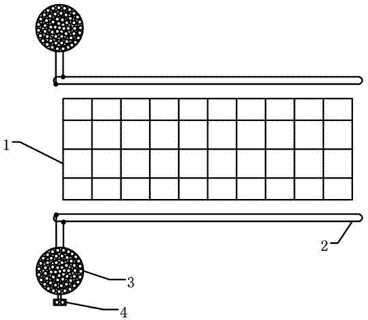
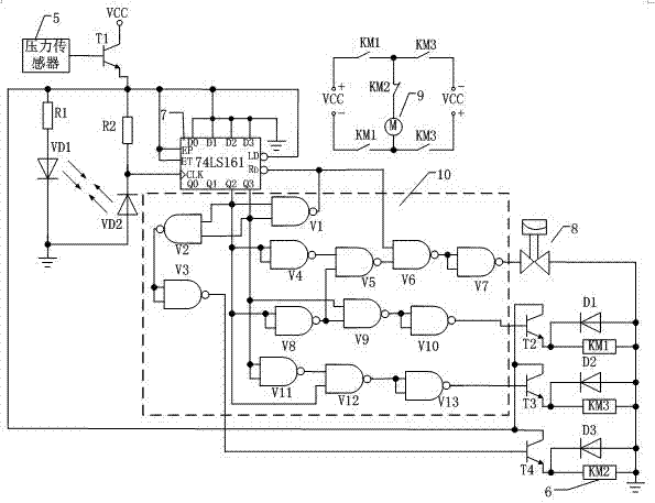
[0019] Embodiment 1: as Figure 1-2 As shown, a construction vehicle tire cleaning device includes a water leakage frame 1, a guide rail 2, a sprinkler 3, a self-reflective infrared tube module 4, and a control circuit; the guide rail 2 is installed on both sides of the water leakage frame 1, and the guide rail 2, the sprinkler 3 is installed, and the self-reflective infrared pipe module 4 is installed on the top of any one of the sprinklers 3; the control circuit includes a pressure sensor 5, a relay 6, a 74LS161 counter 7, a solenoid valve 8, a DC motor 9, The combined logic gate circuit 10 controls the working state of the triode T1 according to the output signal of the pressure sensor 5, thereby controlling the power supply of the subsequent circuit; the self-reflective infrared tube module 4 outputs a control signal to the 74LS161 counter 7, and the output signal of the 74LS161 counter 7 passes through The combined logic gate circuit 10 controls the action of the solenoid...

Embodiment 2

[0020] Embodiment 2: as Figure 1-2 As shown, a construction vehicle tire cleaning device includes a water leakage frame 1, a guide rail 2, a sprinkler 3, a self-reflective infrared tube module 4, and a control circuit; the guide rail 2 is installed on both sides of the water leakage frame 1, and the guide rail 2, the sprinkler 3 is installed, and the self-reflective infrared pipe module 4 is installed on the top of any one of the sprinklers 3;

[0021]The control circuit includes a pressure sensor 5, a relay 6, a 74LS161 counter 7, a solenoid valve 8, a DC motor 9, and a combined logic gate circuit 10, and controls the working state of the triode T1 according to the output signal of the pressure sensor 5, thereby controlling the power supply of the subsequent circuit Situation; self-reflection infrared tube module 4 outputs control signal to 74LS161 counter 7, 74LS161 counter 7 output signal controls solenoid valve 8, relay KM1, relay KM3, relay KM2 action through combination...


PUM


Abstract

The invention relates to a construction vehicle tire cleaning device and belongs to the technical field of automatic control. The construction vehicle tire cleaning device comprises a water leaking frame, guide rails, water sprayers, a self-reflection infrared geminate transistor module and a control circuit; the guide rails are mounted on the two sides of the water leaking frame, the water sprayers are mounted on the guide rails, and the self-reflection infrared geminate transistor module is mounted at the top end of any water sprayer; the control circuit comprises a pressure sensor, relays, a counter, a solenoid valve, a direct-current motor and a combinational logic gate circuit; the self-reflection infrared geminate transistor module outputs a control signal to the counter, and an output signal of the counter controls the solenoid valve, the relay KM1, the relay KM3 and the relay KM2 to act through the combinational logic gate circuit, then controls the water sprayers to spray water and controls the direct-current motor to rotate forwardly or reversely or stop. The construction vehicle tire cleaning device solves the problem that the highway environment is contaminated when a construction vehicle comes in or goes out of a construction site because tires are stained with soil, and the tires of the construction vehicle can be cleaned easily and conveniently.

Description

technical field [0001] The invention relates to a tire cleaning device for construction vehicles, which belongs to the technical field of automatic control. Background technique [0002] When construction vehicles enter and leave the construction site, there will be a lot of mud on the tires. When the construction vehicles drive on the road, they will leave mud on the road and pollute the environment. At present, some construction departments use artificial water pipes to clean the tires. This method Time-consuming and labor-intensive, it brings a lot of inconvenience to the site managers. Contents of the invention [0003] The technical problem to be solved by the present invention is to propose a construction vehicle tire cleaning device, which uses a control circuit to monitor the entry and exit of construction vehicles in real time; when the construction vehicle stays on the leaking frame, the DC motor is turned forward by outputting a control signal through the pressu...

Claims


Application Information

Patent Timeline
Patent Type & Authority Patents(China)
IPC IPC(8): B60S3/04
CPCB60S3/042
Inventor 刘明漆超
Owner KUNMING UNIV OF SCI & TECH
Why Eureka
Try Eureka