An impinging flow hydraulic acoustic cavitation loop reactor
A loop reactor, flow hydraulic technology, applied in chemical instruments and methods, water/sewage treatment, special compound water treatment, etc., can solve the problem of low cavitation intensity, and achieve low cavitation energy consumption, convenient operation and cost. low effect
- Summary
- Abstract
- Description
- Claims
- Application Information
AI Technical Summary
Problems solved by technology
Method used
Image

Examples
Embodiment 1
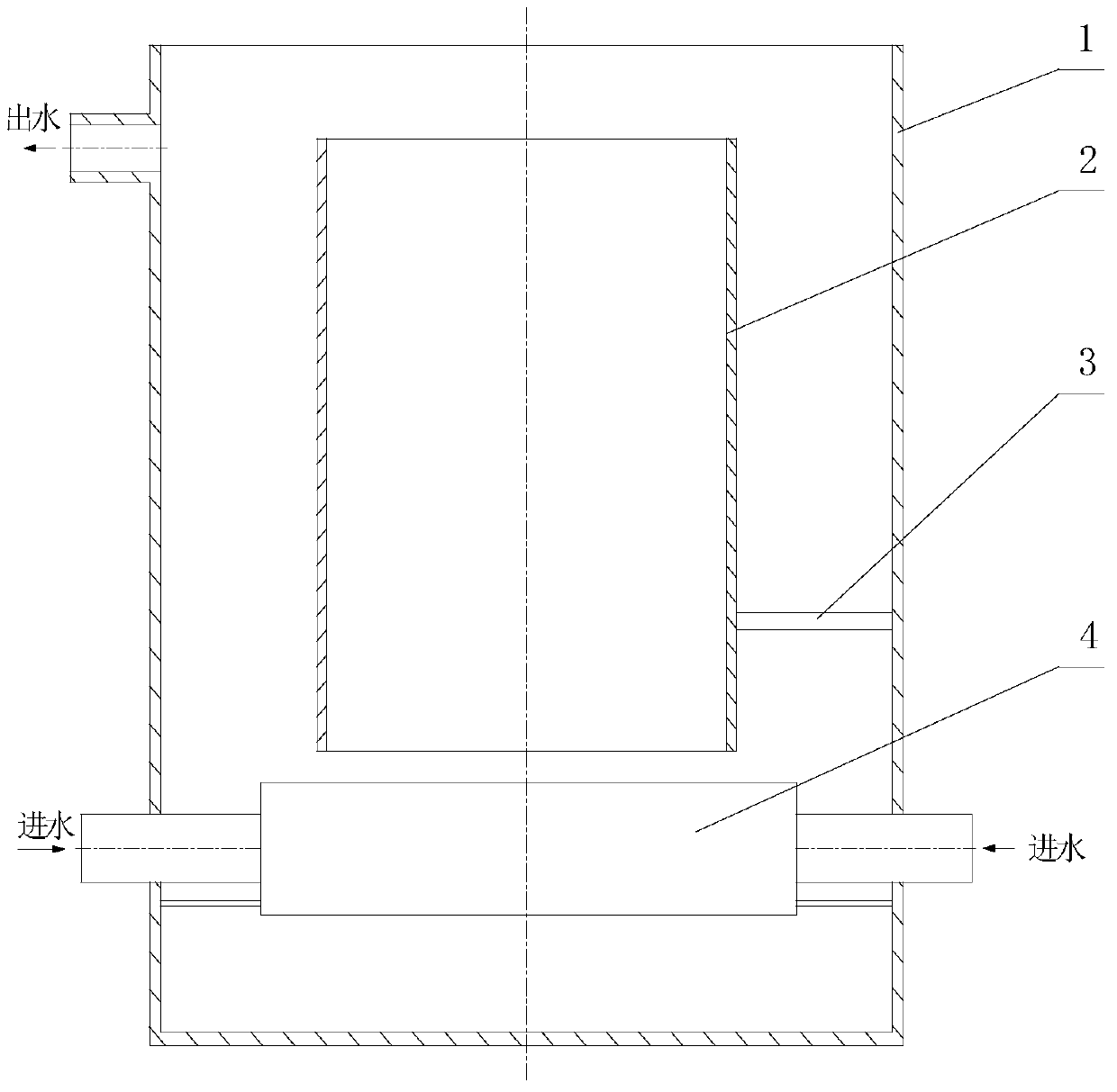
[0017] Depend on figure 1 It can be seen that the hydroacoustic cavitation loop reactor of this embodiment is composed of an outer cylinder 1 , a guide cylinder 2 , a fixed rod 3 and a hydrophonic generator 4 .
[0018] The outer cylinder 1 of the present embodiment is a cylindrical structure with a diameter of 60 cm. A water outlet is opened on the upper side wall of the outer cylinder 1. The inner cavity of the outer cylinder 1 is 45 cm from the bottom of the outer cylinder 1 through the fixed rod 3 and the outer cylinder 1. A guide tube 2 with a diameter of 50 cm is fixedly installed on the threaded fastener. The central axis of the guide tube 2 coincides with the central axis of the outer tube 1. The height of the lower port of the guide tube 2 from the bottom of the outer tube 1 is 20 cm. , a hydraulic sounder 4 is horizontally installed directly below the guide tube 2 through a fixed rod 3 .
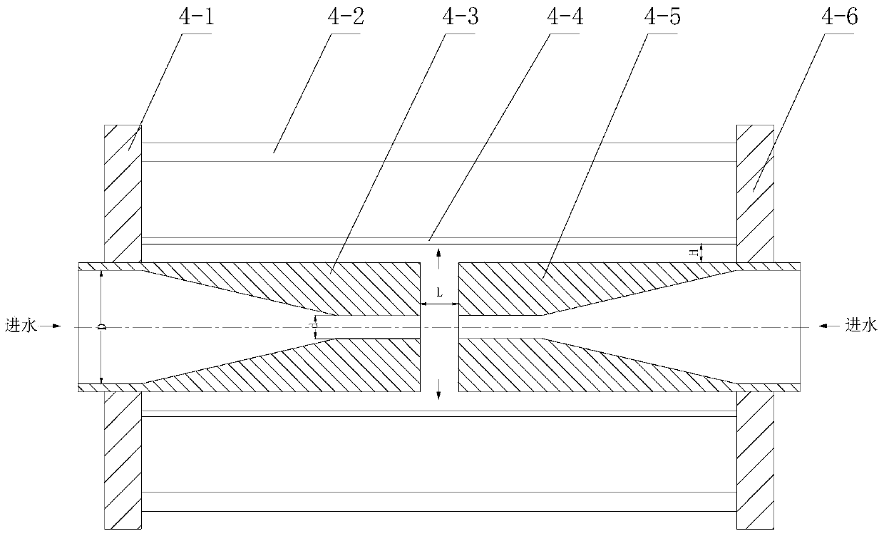
[0019] see figure 2 , the hydraulic sounder 4 of the present embodiment is ...
Embodiment 2
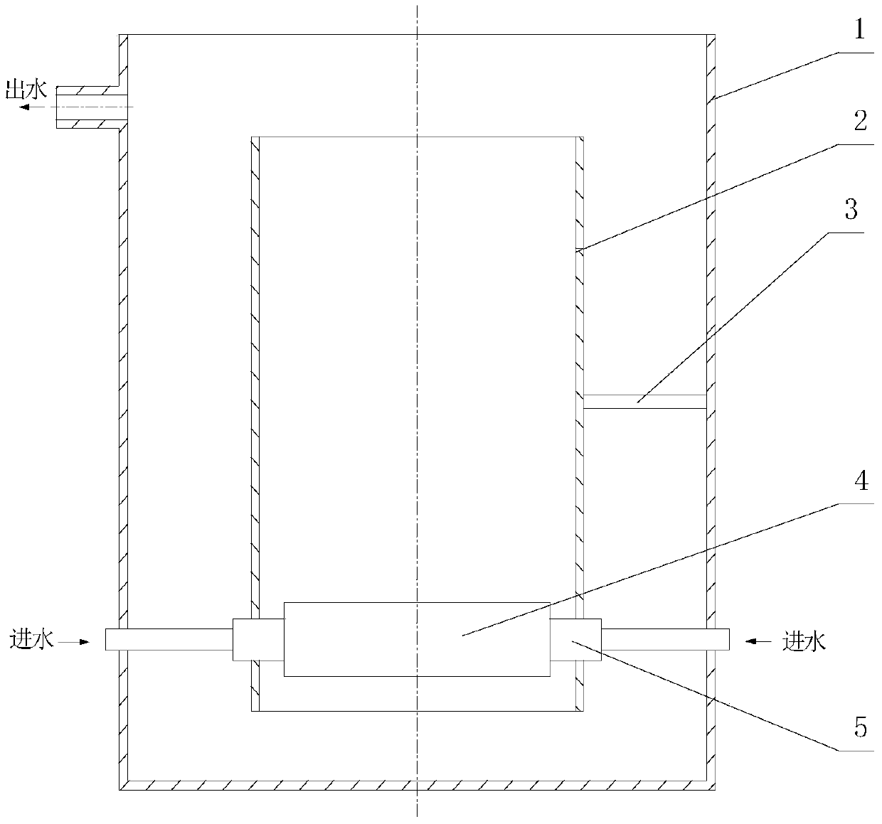
[0023] see image 3 , the hydraulic sounder 4 of the present embodiment is directly fixed on the side wall of the bottom end of the guide tube 2, that is, joints 5 are respectively installed at the same height on the opposite side walls of the guide tube 2 at the bottom, and the joints 5 is a commonly used water pipe joint, which can facilitate the disassembly and assembly of the hydraulic sounder 4, that is, one end of the joint 5 is connected to the water inlet pipe extending to the outside of the outer cylinder 1, and the other end is respectively connected to the first nozzle 4-3 of the hydraulic sounder 4. , The second nozzle 4-5 communicates.
[0024] The outside of the first nozzle 4-3 of this embodiment is a straight pipe structure, and the inside is connected by a tapered pipe section and a straight pipe section to form a convergent flow channel. The central axis of the first nozzle 4-3 is perpendicular to the central axis of the outer cylinder 1 , and the height of ...
Embodiment 3
[0028] The hydraulic sounder 4 of the present embodiment is processed with a central installation hole at the center position of the first fixed plate 4-1, and the first nozzle 4-3 is installed with a screw thread in the central installation hole, and the first nozzle 4-3 The central axis is perpendicular to the central axis of the outer cylinder 1, and the height of the outer wall of the first nozzle 4-3 from the bottom of the outer cylinder 1 is 10cm. The outside of the first nozzle 4-3 of this embodiment is a straight pipe structure, and the inside is made of a cone. The conical pipe section and the straight pipe section are connected to form a convergent flow channel. The length of the internal tapered pipe section is 38mm, the inner diameter D of the water inlet port is 8mm, the inner diameter d of the water outlet port is 5.6mm, d / D=0.7, and the straight pipe section is connected at At the outlet end of the tapered pipe section, the inner diameter of the straight pipe sec...
PUM
| Property | Measurement | Unit |
|---|---|---|
| distance | aaaaa | aaaaa |
| height | aaaaa | aaaaa |
| diameter | aaaaa | aaaaa |
Abstract
Description
Claims
Application Information
 - R&D
- Intellectual Property
- Life Sciences
- Materials
- Tech Scout
- Unparalleled Data Quality
- Higher Quality Content
- 60% Fewer Hallucinations
Browse by: Latest US Patents, China's latest patents, Technical Efficacy Thesaurus, Application Domain, Technology Topic, Popular Technical Reports.
© 2025 PatSnap. All rights reserved.Legal|Privacy policy|Modern Slavery Act Transparency Statement|Sitemap|About US| Contact US: help@patsnap.com