Ultrasonic cleaning device of washing machine
A technology for cleaning devices and washing machines, which can be applied to washing devices, textiles and papermaking, household appliances, etc., and can solve problems such as poor cleaning effect
- Summary
- Abstract
- Description
- Claims
- Application Information
AI Technical Summary
Problems solved by technology
Method used
Image

Examples
Embodiment 1
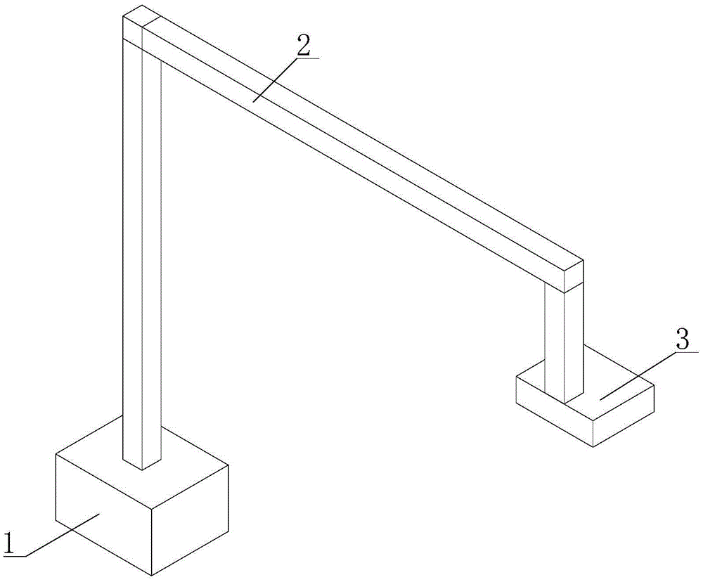
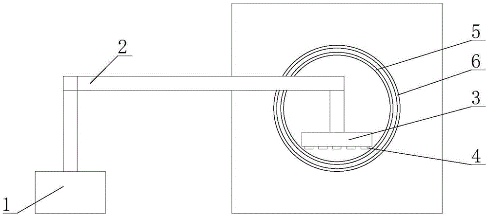
[0073] figure 1 It is a structural schematic diagram of the washing machine ultrasonic cleaning device for drum type washing machine or front-loading washing machine of embodiment 1: figure 2 It is a schematic diagram of the state of the washing machine ultrasonic cleaning device for a drum-type washing machine or a front-loading washing machine of Embodiment 1 after being put into the washing machine; in the figure, the meanings of each reference mark are as follows: 1, ultrasonic generator; 2, mechanical connection 3. Vibrator mounting plate; 4. Ultrasonic vibrator; 5. Inner barrel; 6. Outer barrel.
[0074] A washing machine ultrasonic cleaning device for a drum-type washing machine or a front-loading washing machine, comprising:
[0075] The vibrator mounting plate 3 and the ultrasonic vibrator 4 are arranged horizontally for penetrating into the inner tub 5 of the washing machine;
[0076]The ultrasonic vibrator 4 is installed on the lower surface of the vibrator mount...
Embodiment 2
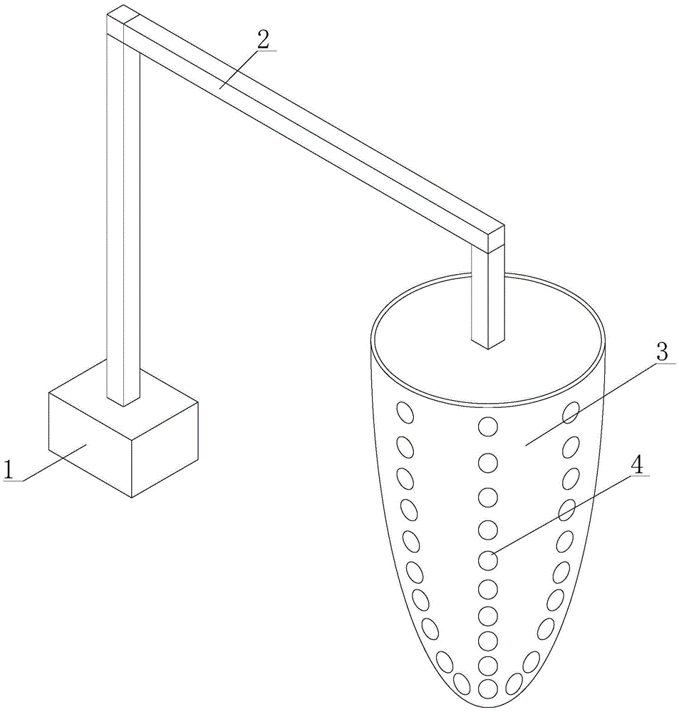
[0085] image 3 It is the structural representation of the washing machine ultrasonic cleaning device for the pulsator type washing machine or the inclined bucket type washing machine or the top-loading washing machine of embodiment 2: Figure 4 It is a schematic diagram of the state of the washing machine ultrasonic cleaning device for the pulsator washing machine or the inclined bucket washing machine or the top-loading washing machine of embodiment 2 after being put into the washing machine; Figure 4 In , the half-section drawing method is used for the inner and outer tubs of the washing machine.
[0086] In the figure, the meanings of the reference signs are as follows: 1. Ultrasonic generator; 2. Mechanical connection device; 3. Vibrator mounting plate; 4. Ultrasonic vibrator; 5. Inner barrel; 6. Outer barrel.
[0087] A washing machine ultrasonic cleaning device for a pulsator washing machine or an inclined bucket washing machine or a top-loading washing machine, compr...
Embodiment 3
[0097] Figure 5 It is the partial structure schematic diagram of embodiment 3. In the figure, the definitions of the same reference signs in the accompanying drawings used in embodiment 2 still continue to use the definition in embodiment 2, and the meanings of each reference sign newly appearing with respect to the accompanying drawings of embodiment 2 are as follows: 9, Rotating shaft; 10, photoelectric encoder; 11, frame; 16, driving motor.
[0098] The difference between this embodiment and embodiment 2 is that the vibrator mounting plate 3 is not fixedly installed on the mechanical connection device, but:
[0099] The vibrator mounting plate 3 is installed on the rotating shaft 9 in a keyed manner, the rotation axis of the vibrator mounting plate 3 is the same as the rotation axis of the inner barrel of the washing machine, and the frame 11 is fixedly connected with the connecting device.
[0100] The ultrasonic vibrator 4 is installed at the junction of two planes and...
PUM
 Abstract
Description
Claims
Application Information
 - R&D
- Intellectual Property
- Life Sciences
- Materials
- Tech Scout
- Unparalleled Data Quality
- Higher Quality Content
- 60% Fewer Hallucinations
Browse by: Latest US Patents, China's latest patents, Technical Efficacy Thesaurus, Application Domain, Technology Topic, Popular Technical Reports.
© 2025 PatSnap. All rights reserved.Legal|Privacy policy|Modern Slavery Act Transparency Statement|Sitemap|About US| Contact US: help@patsnap.com