Bank protecting wall

A protective wall and prestressing technology, which is applied in the direction of coastline protection, etc., can solve the problems of inconvenient pouring of embankment protective walls, mechanical properties that cannot meet actual needs, and expensive construction of embankment protective walls. The effect of construction period, humanized design and simple and reasonable overall structure

Active Publication Date: 2016-05-04
俞向阳
View PDF9 Cites 9 Cited by
  • Summary
  • Abstract
  • Description
  • Claims
  • Application Information

AI Technical Summary

Problems solved by technology

The load-carrying elements used in these two published patent applications are all made of hot rails. In order to make such a club-shaped connecting tail section, rough rolling, finishing rolling and other processes are required, and the cost of expensive roll sets is staggering.
[0005] The third is to adopt the embankment protection wall formed by the H-type support piles connected successively through the rib groove insertion structure, such as the Chinese invention patent "H-type support piles" whose patent number is ZL201320461012.5 (notification number is CN203559411U). "Connection Structure" discloses such a form of embankment protective wall. Since the flange width of each H-shaped retaining pile is small, a large number of H-shaped retaining piles are required to be spliced ​​to form a long-distance embankment protective wall. Formation, while the manufacturing price of each H-shaped support pile is relatively high, which leads to the high cost of building the entire embankment protection wall
However, it is inconvenient to pour out steps for the embankment protection wall built with concrete prefabricated piles.
In addition, the mechanical properties of the existing embankment protection walls often fail to meet the actual needs, and their construction costs are too high and the construction period is long

Method used


Image

  • Bank protecting wall
  • Bank protecting wall
  • Bank protecting wall

Examples


Embodiment Construction

[0029] The present invention will be further described in detail below in conjunction with the accompanying drawings and embodiments.

[0030] Such as Figure 1~4 Shown is the first embodiment of the present invention.

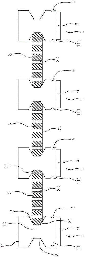
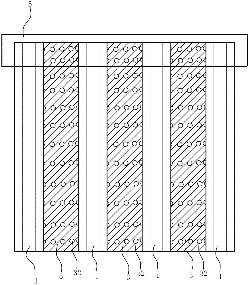
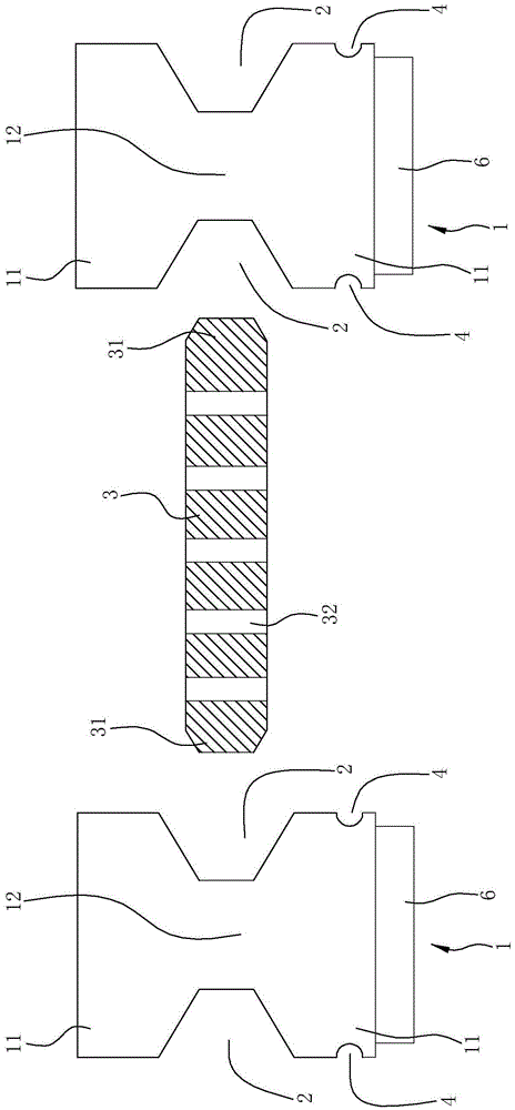
[0031] A bank embankment protection wall, including a plurality of H-shaped prestressed concrete piles 1 inserted into the soil of the embankment at intervals. The H-shaped prestressed concrete piles 1 are reinforced concrete structures with a length of 8 meters to 15 meters and are produced in a factory In the production process, prestress is applied to the steel bars in the pile body.

[0032] The cross section of the H-type prestressed concrete pile 1 is H-shaped formed by two flanges 11 and the web 12 connecting the two flanges 11. The grooves 2 extending along the length direction of the pile body are formed on both sides of the pile body, and a prefabricated insert 3 is arranged between two adjacent H-shaped prestressed concrete piles 1. 2, the insert...


PUM


Abstract

The invention relates to a bank protecting wall. The bank protecting wall is characterized by comprising a plurality of H-shaped prestressed concrete piles inserted into soil at intervals; the cross section of each H-shaped prestressed concrete pile is in an H-shape formed by two flanges, and a web connected with the two flanges, and the two flanges and the web form, on two sides of the H-shaped prestressed concrete pile, groove portions extending in the length direction of the pile body; a prefabricated spile is arranged between every two adjacent H-shaped prestressed concrete piles, and left and right sides of the prefabricated spile are inserted into the groove portions; a plurality of projecting or sunken pedal portions for people to tread are arranged on an outer wall of each flange, and the plurality of pedal portions are arranged at intervals in the length direction of the corresponding H-shaped prestressed concrete pile. The bank protecting wall is simple and reasonable in overall structure without complex connection structure; the construction of the bank protecting wall is better facilitated, and the construction period is greatly shortened. By providing the pedal portions, a person falling down can climb up along the pedal portions, and therefore, the design, in safety, of the bank protecting wall employing the prefabricated piles is user-friendlier.

Description

technical field [0001] The invention relates to an enclosure structure technology suitable for civil engineering, water conservancy and municipal engineering, etc., in particular to a bank protection wall, which is mainly used for the protection of banks of rivers, lakes and seas. Background technique [0002] Large-scale underground buildings, quay walls of ports and revetments of rivers, etc. During construction, these buildings need to protect themselves or the foundations of surrounding buildings. The requirements for the embankment protection wall are: high rigidity wall, ecological environment and easy construction. Of course, under the premise of meeting the above conditions, the lower the cost, the better. [0003] There are three types of bank protection walls commonly used at present. The first type is to use multiple reinforced concrete circular piles combined with cement mixing piles and then insert the soil to form an enclosure wall. There are also multiple T-sh...

Claims


Application Information

Patent Timeline
IPC IPC(8): E02B3/12
CPCE02B3/12
Inventor 俞向阳
Owner 俞向阳
Why Eureka
Try Eureka