Rubber molding machine

A technology for a rubber molding machine and a glue injection machine, which is applied in the field of mechanical processing equipment, can solve the problem that the upper mold and the lower mold lack the positioning and limit functions, increase the overall working time of the rubber molding machine, and cannot realize the positioning function of the upper mold and the lower mold. and other problems, to achieve the effect of shortening the overall working time, high market promotion value, and simple and reasonable overall structure

Active Publication Date: 2018-02-09
JIANGSU SAIER RUBBER CO LTD
View PDF6 Cites 1 Cited by
  • Summary
  • Abstract
  • Description
  • Claims
  • Application Information

AI Technical Summary

Problems solved by technology

[0002] Rubber molding machine is the most widely used rubber material molding equipment at present. It mainly uses the principle of hot-press molding rubber to realize the molding of rubber products. In traditional rubber molding machines, the upper mold and the lower mold are driven by the power system. When moving down, there is no effective positioning and limiting function for the upper mold and the lower mold, so that the upper mold and the lower mold move a large stroke in the invalid working area, which not only wastes energy, but also increases the overall working time of the rubber molding machine , will cause damage to the rubber molding machine body; as the patent application number CN03230379.3 discloses a hydraulically controlled rubber injection molding machine, including a vulcanizer, a mold opening and closing pull rod, an upper and lower plate, an upper and lower electric heating plate, and an injection molding machine. Cylinder and injection rod, the glue injection cylinder with piston rod is installed on the upper plate, the protruding end of the piston rod faces the injection cylinder, and the piston rod is provided with two travel switches or a displacement scale on the wall in the vertical direction. , its structure is single, and it is impossible to realize the effective positioning function of the upper mold and the lower mold; another example is that the patent application number 201120237311.1 discloses a double-top double-layer rubber molding machine, including: machine base; middle template, the middle The rear end of the template can be movably connected to the lower template through a connecting member, and the middle template can be opened and closed relative to the lower template through the connecting member; the middle template lifting seat, the middle template lifting seat includes a left lifting seat and a The right lifting seat, the left lifting seat and the right lifting seat are respectively arranged on the left and right sides of the middle formwork, providing the power for the middle formwork to be opened and closed relative to the lower formwork; the upper formwork, the left and right sides of the upper formwork There are left guide rail plate and right guide rail plate arranged on the machine base to provide the upper template to slide according to the predetermined track. Although this scheme can improve the working efficiency of the rubber molding machine, its stability is poor and the degree of automation is low, so it is not suitable for large-scale Extended use

Method used


Image

  • Rubber molding machine
  • Rubber molding machine
  • Rubber molding machine

Examples


Embodiment Construction

[0026] In order to make the objectives, technical solutions, and advantages of the embodiments of the present invention clearer, the technical solutions in the embodiments of the present invention will be described clearly and completely in conjunction with the accompanying drawings in the embodiments of the present invention. Obviously, the described embodiments It is a part of the embodiments of the present invention, not all of the embodiments. Based on the embodiments of the present invention, all other embodiments obtained by those of ordinary skill in the art without creative work shall fall within the protection scope of the present invention.

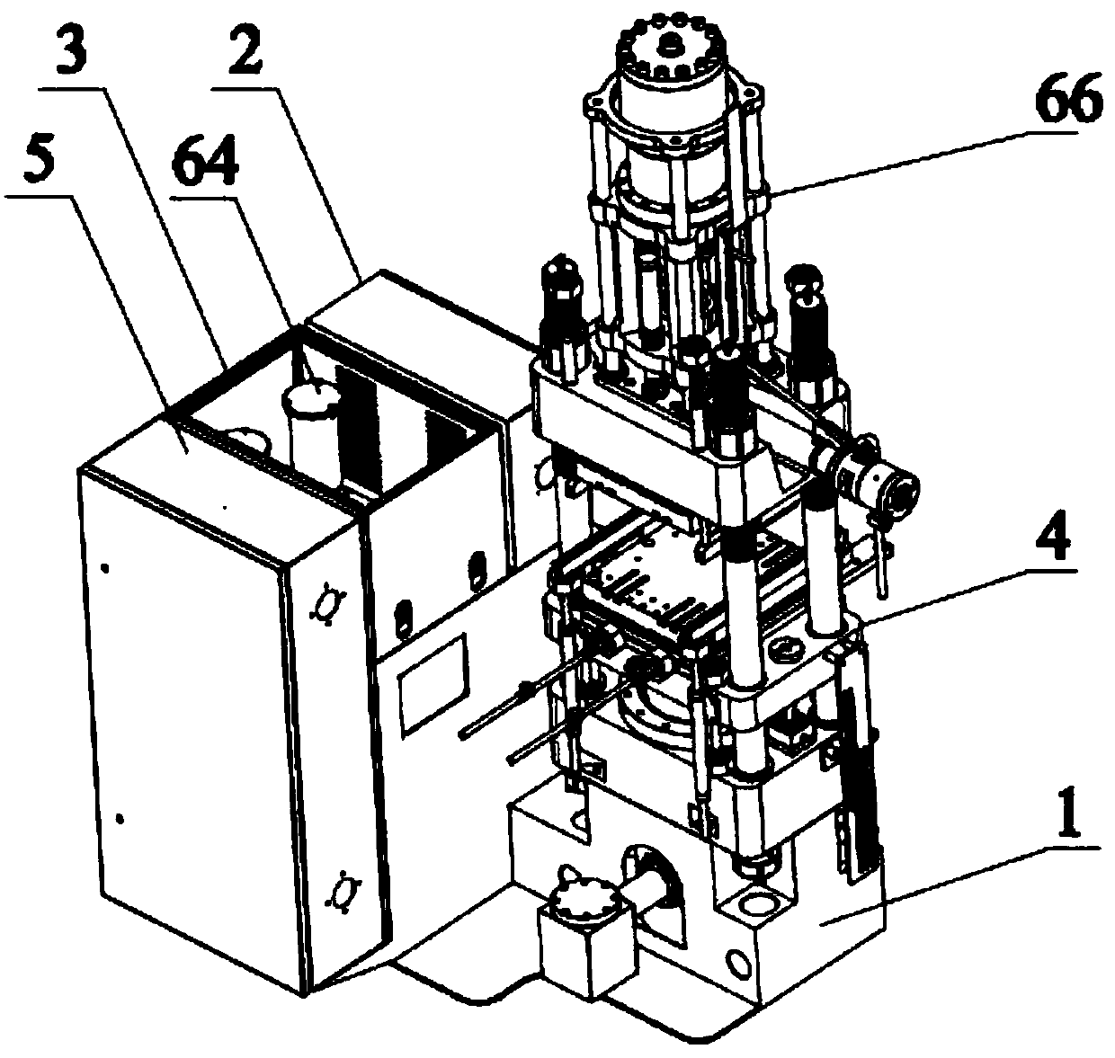
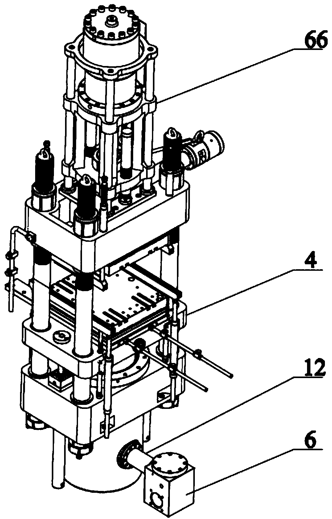
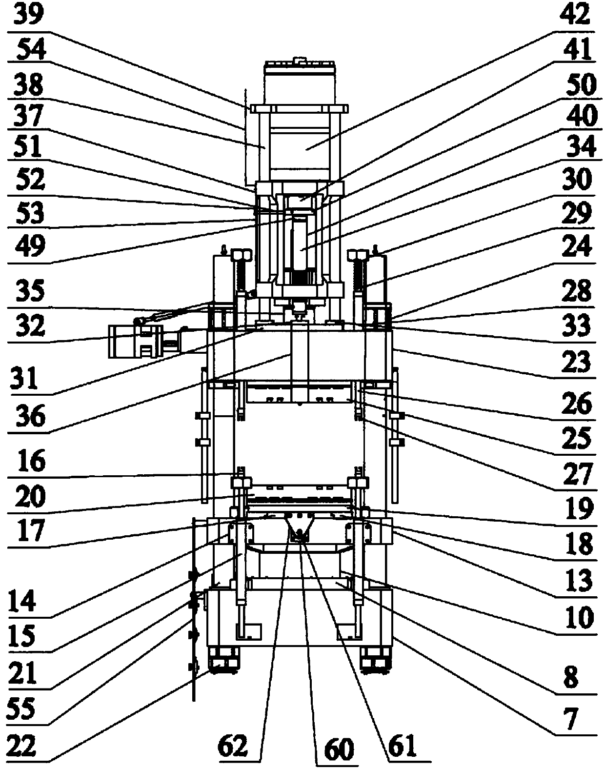
[0027] Such as Figure 1-5 As shown, a rubber molding machine includes a main frame 1, an electric control box 2, a heating system box 3, and a glue injection machine 4. The main frame 1 is provided with a window ventilation plate, and one side of the main frame 1 is provided with an electric box 5 To further optimize this plan, th...


PUM


Abstract

The invention provides a rubber molding machine. An electric box is arranged on one side of a main frame; a heating system box, an electric control box and a rubber injecting machine are arranged at the top of the main frame; the whole system operation is controlled through the electric control box, so that the automation degree is high, and the whole mechanism is simple and reasonable, and achieves higher market popularization value; an upper mold and a lower mold move along with an upper mold fixed plate and a lower mold fixed plate in use; a back positioning rod achieves a positioning effect, and an adjusting plate slide piece achieves a limiting effect, so that the upper mold and the lower mold are always located in an effective working area, the energy is saved, and the total workingtime of the rubber molding machine is greatly shortened; meanwhile, thermal insulation asbestos plates and thermal insulation cushion plates are arranged between a middle slide fixed plate and the lower mold fixed plate and between an upper fixed base and the upper mold fixed plate to achieve better thermal insulation effect; and a cooler connected with a hot oil tank is used for assistance to effectively prevent damage of a main body of the rubber molding machine by higher temperature.

Description

Technical field [0001] The invention belongs to the technical field of mechanical processing equipment, and specifically relates to a rubber molding machine. Background technique [0002] Rubber molding machine is currently the most widely used rubber material molding equipment. It mainly uses the principle of molds to heat and press rubber to form rubber products. In traditional rubber molding machines, the upper and lower molds are driven by the power system. When moving downwards, the upper and lower molds lack effective positioning and limit functions, which makes the upper and lower molds move a larger stroke in the invalid working area, which not only wastes energy, but also increases the overall working time of the rubber molding machine , It will even cause damage to the body of the rubber molding machine; for example, the patent application number CN03230379.3 discloses a hydraulically controlled rubber injection molding machine, including a vulcanizer, open and close mo...

Claims


Application Information

Patent Timeline
IPC IPC(8): B29C45/26B29C33/30B29C45/73B29C45/84B29C45/80
CPCB29C45/2606B29C45/73B29C45/80B29C45/84B29C2945/76568
Inventor 钱海燕
Owner JIANGSU SAIER RUBBER CO LTD
Why Eureka
Try Eureka