Overflow control system

A control system and overflow technology, applied in waterway systems, climate change adaptation, drainage structures, etc., can solve the problems of downstream water quality and perception adverse effects, waterlogging or flood disasters, water pollution, etc., to prevent the phenomenon of river water level backflow , Reduce management and maintenance costs, save manpower and material resources

Inactive Publication Date: 2016-05-04
SHANGHAI URBAN CONSTR DESIGN RES INST GRP CO LTD
View PDF8 Cites 1 Cited by
  • Summary
  • Abstract
  • Description
  • Claims
  • Application Information

AI Technical Summary

Problems solved by technology

[0005] First, due to the high concentration of pollutants in the initial rainwater, various pollutants (especially particulate pollutants) are also mixed in the ordinary combined sewage. The rainwater (or combined sewage) of the waste is directly discharged into the river without treatment, causing water pollution and adversely affecting the water quality and appearance of the downstream water body
[0006] Second, the setting of a fixed-height overflow weir raises the water level of the pipeline system, which may cause waterlogging or flood disasters in case of super-heavy rainfall, reducing the flood control and disaster reduction capabilities of the original system
[0007] Third, because the height of the overflow weir is fixed, when the water level of the river is high, the overflow weir cannot prevent the river from backflowing, which may easily cause waterlogging or flood disasters, resulting in unnecessary losses

Method used


Image

  • Overflow control system
  • Overflow control system

Examples


Embodiment Construction

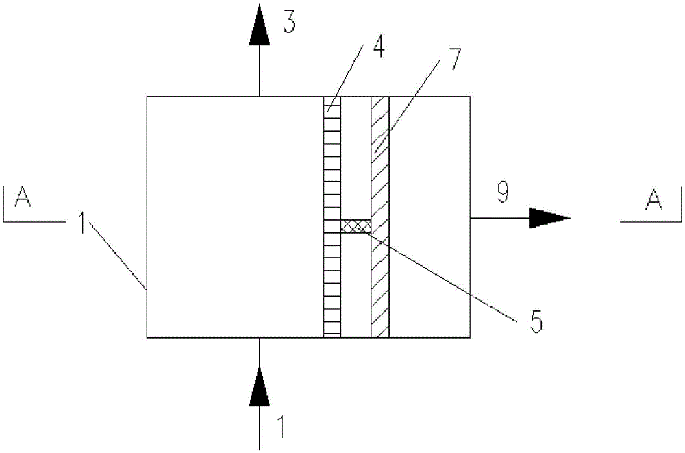
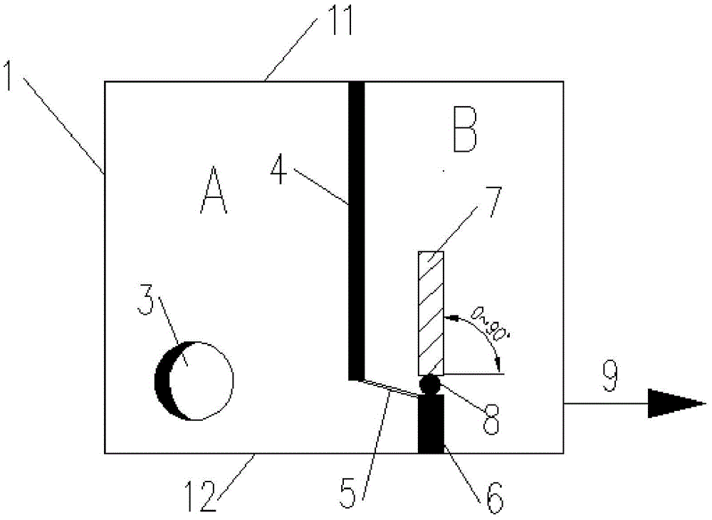
[0024] Such as figure 1 and figure 2 As mentioned above, this embodiment provides an overflow control system, which includes an overflow well 1 , a water inlet pipe 2 and an outlet pipe 3 connected to the overflow well 1 .

[0025] Such as figure 1 As shown, the system also includes a first partition wall 4 extending downward from the top 11 of the overflow well. The first partition wall 4 separates the overflow well 1 into a confluence system A and an overflow system B through which the bottom penetrates. The water inlet pipe 2 and the outlet pipe 3 are set in the confluence system A.

[0026] Such as figure 2 As shown, the overflow system is provided with a second partition wall 6, the second partition wall 6 extends upward from the bottom 12 of the overflow well, and the top of the second partition wall 6 is provided with an overflow that can automatically adjust the height under the action of the hydraulic pressure difference. flow weir7. B in the overflow system is...


PUM


Abstract

The invention discloses an overflow control system, which at least comprises an overflow well, a water inlet pipe, a water outlet pipe and a first separation wall, wherein the water inlet pipe and the water outlet pipe are communicated with the overflow well; the first separation wall downwards extends from the top of the overflow well; the overflow well is separated into a flow merging system and an overflow system by the first separation wall; the bottoms of the flow merging system and the overflow system are communicated; the water inlet pipe and the water outlet pipe are arranged in the flow merging system; an overflow pipe communicated with a riverway is arranged in the overflow system; a second separation wall is also arranged in the overflow system; the second separation wall upwards extends from the bottom of the overflow well; the top of the second separation wall is provided with an overflow weir capable of automatically regulating the height under the effect of hydraulic pressure differences; and when the hydraulic pressure differences at the two sides of the overflow weir are great, rain sewage flows into the overflow system from the flow merging system, flows across the overflow weir to flow into the overflow pipe, and is discharged from the overflow pipe. The overflow control system has the advantages that the structure is simple; particle pollutants in the sewage can be blocked; and the flood prevention and disaster reduction capability of the existing system is not influenced.

Description

technical field [0001] The invention relates to the technical field of water supply and drainage, in particular to an overflow control system. Background technique [0002] Water pollution is a major problem in today's society. If untreated combined sewage or rainwater is directly discharged into rivers and lakes, it will cause great pollution to the water environment. With the public's increasing requirements for the quality of urban water environment, the overflow pollution of the drainage system has attracted more and more attention from the government, and various control systems to prevent overflow have also emerged as the times require. [0003] In order to solve the above technical problems, engineering personnel usually set up overflow wells at the river overflow outlets of the drainage system, and set a fixed-height overflow weir in the overflow wells to solve the problem of rainwater overflow pollution. [0004] But, the overflow well of above-mentioned structure ...

Claims


Application Information

Patent Timeline
Patent Type & Authority Applications(China)
IPC IPC(8): E03F5/042
CPCE03F5/042Y02A30/60
Inventor 胡龙胡世琴唐群王碧波
Owner SHANGHAI URBAN CONSTR DESIGN RES INST GRP CO LTD
Why Eureka
Try Eureka