Modular integrated building system

A building system and modular technology, applied in the direction of architecture, building components, building structures, etc., can solve problems such as difficult remedial measures, disengagement of wall panel laps, and cracking of formwork, so as to avoid wall damage and ensure rigidity and the firmness of the connection, the effect of ensuring stability

Inactive Publication Date: 2016-05-04
BOEN SOLAR TECH
View PDF14 Cites 11 Cited by
  • Summary
  • Abstract
  • Description
  • Claims
  • Application Information

AI Technical Summary

Problems solved by technology

[0004] However, during the construction of the building formwork of this kind of structure, concrete is poured in the cavity. Due to manual vibration and the relatively large lateral pressure of the concrete itself, the formwork often expands.
Once expansion occurs, formwork will crack and panel laps will come off, making remedial actions difficult and time consuming

Method used


Image

  • Modular integrated building system
  • Modular integrated building system
  • Modular integrated building system

Examples


Embodiment 2

[0052] The structure and principle of this embodiment are basically the same as that of Embodiment 1, the difference is that:

[0053] like Figure 11 As shown, each wallboard panel unit 1a has lapping arms 1a3 and snapping arms 1a4 respectively located on both sides, and the fastener 3 includes a fastening screw 3a, and the fastening screw 3a passes through the wallboard panel unit 1a. The snap-fitting arm 1a3 and the lapping arm 1a4 of the adjacent wallboard panel unit 1a are connected to the support 3 . Certainly, the overlapping arm 1a3 and the buckling arm 1a4 may be L-shaped extension arms, or other feasible ways. Of course, in the actual production process, in order to prevent the two wallboard panel units 1a from being too close together, causing the wall filler 6 to have no expansion space and damage the wallboard panel 1, a gap between two adjacent wallboard panel units 1a Generally, there will be a certain gap, and when the final completion, in order not to affect...

Embodiment 3

[0055] The structure and principle of this embodiment are basically the same as that of Embodiment 1, the difference is that:

[0056] like Figure 12 As shown, the fastener 3 includes a fastening screw 3a, and two adjacent wallboard panel units 1a are connected to the same support 3 through at least one fastening screw 3a. The fastening screws 3a can be used directly on each wallboard panel unit 1a to realize the connection, which can make the processing of the wallboard panel unit 1a easier.

Embodiment 4

[0058] The structure and principle of this embodiment are basically the same as that of Embodiment 1, the difference is that:

[0059] like Figure 13 As shown, the connecting pipe is a square pipe, and the square pipe can also achieve the purpose of smooth flow diversion, as long as one of the edges of the square pipe is set downward, that is, the sharper side of the pipe is set downward, and there is an inclination The diversion auxiliary surface is sufficient.


PUM


Abstract

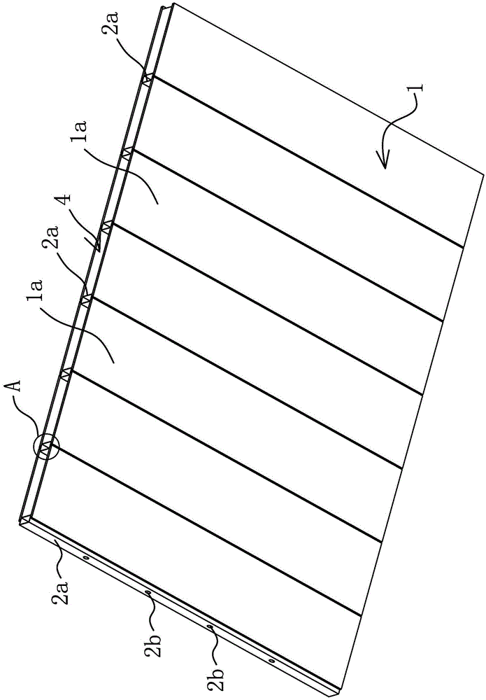
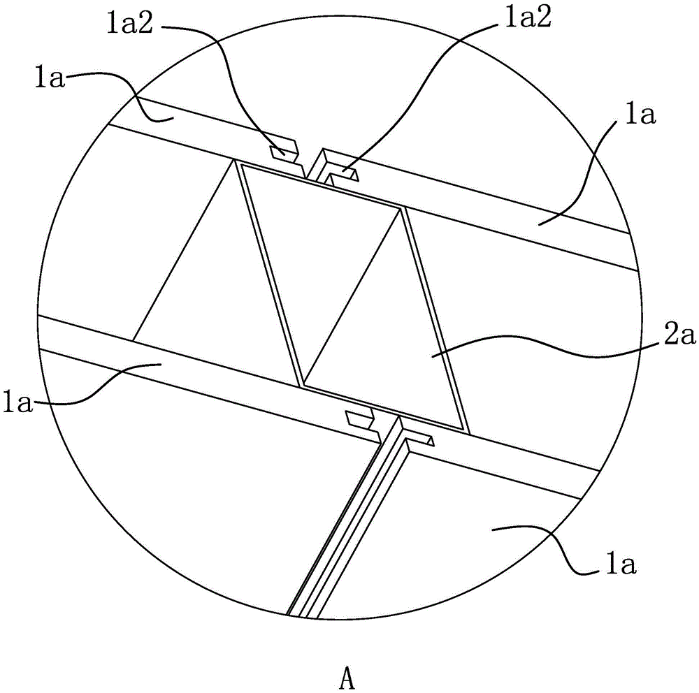
The invention provides a modular integrated building system and belongs to the technical field of buildings. The system solves the problem of an existing non-dismantling building template that the template can crack or damage in use. The modular integrated building system with an improved structure comprises two wallboard panels arranged in a spaced mode, a latticed metal frame is arranged between the two wallboard panels, the metal frame is composed of a plurality of vertically arranged strip-shaped supporting parts and a plurality of horizontally arranged connecting pipes, each supporting part is provided with connecting planes on two sides, the connecting planes face the wallboard panels and are attached to the wallboard panels, the connecting pipes penetrate through the supporting parts and are fixedly connected with the supporting parts, the wallboard panels are fixedly connected to the supporting parts of the metal frame through fasteners, and a cavity filled with wall filler is formed between the two wallboard panels. By the adoption of the modular integrated building system with the improved structure, expansion or damage of a wall can be effectively avoided.

Description

technical field [0001] The invention belongs to the technical field of buildings, and relates to an integrated building system, in particular to a modular integrated building system. Background technique [0002] Building formwork is a temporary support structure, which is manufactured according to the design requirements, so that the concrete structure and components can be formed according to the specified position and geometric size. It is an important construction method in structural construction. The improvement of building formwork technology will reduce the impact on engineering construction. It is of great significance to save costs, save labor and speed up the progress of the project and improve the level of construction. Existing building formwork is generally wood formwork or steel formwork, no matter the wood formwork or steel formwork has the problem of strong adhesion with concrete and difficult demoulding, so when the wall is formed, the wood formwork or stee...

Claims


Application Information

Patent Timeline
Patent Type & Authority Applications(China)
IPC IPC(8): E04B2/86
CPCE04B2/8629
Inventor 刘至国甘汉南梅未
Owner BOEN SOLAR TECH
Why Eureka
Try Eureka