
Free piston linear electric generator

A linear generator and piston type technology, applied in the direction of engine components, machines/engines, mechanical equipment, etc., can solve problems such as difficult control, complex structure, and unstable compression ratio

Inactive Publication Date: 2016-05-04
裘根富
View PDF0 Cites 4 Cited by
  • Summary
  • Abstract
  • Description
  • Claims
  • Application Information

AI Technical Summary

Problems solved by technology

[0002] Existing open free piston generators, such as opposed piston generators, are characterized in that the vibration is stable, but piston synchronization is difficult and the compression ratio is unstable; as double-headed piston generators, it is characterized in that the No rebound device is needed, but the vibration is relatively large, and the timing of intake and exhaust is difficult to control; such as a single-piston generator, it is characterized in that the structure is simple, the cost is low, the control is relatively easy, and the vibration is between the opposed piston and the double piston. between the head pistons, but the structure is relatively complex, and high-temperature working fluid is required. Therefore, it is necessary to invent a free-piston generator with simple structure, smaller size, lower vibration, and higher efficiency to make the system more stable and reliable. get promoted

Method used


Image

  • Free piston linear electric generator
  • Free piston linear electric generator
  • Free piston linear electric generator

Examples


Embodiment 1

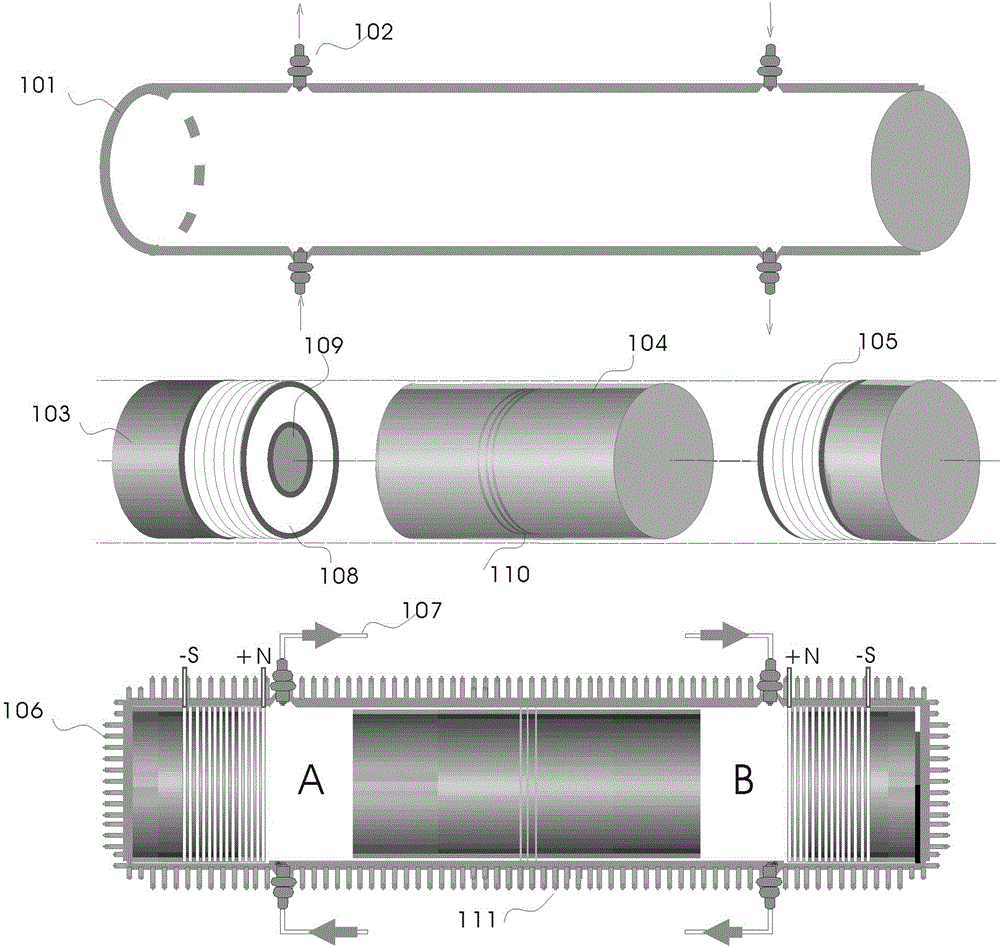
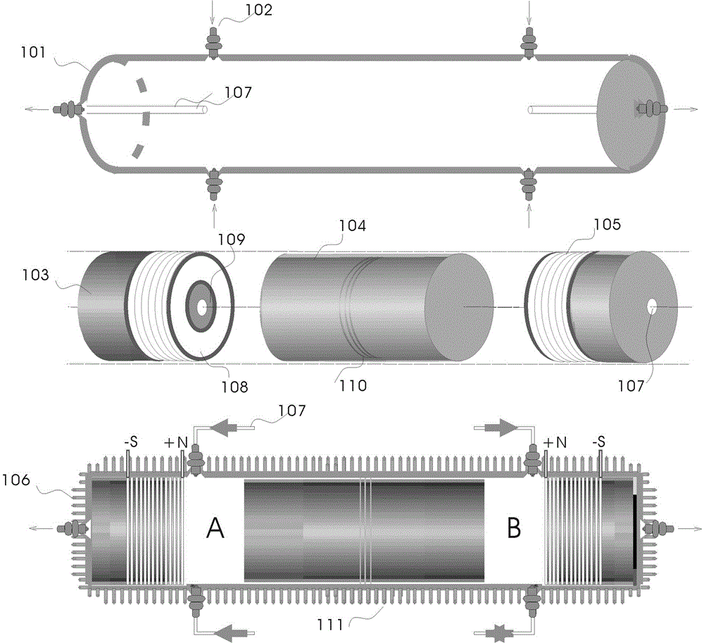
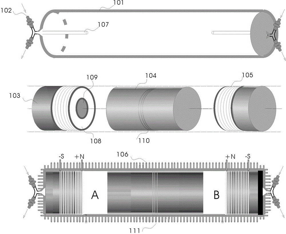
[0041] A free-piston linear generator, firstly, the operator starts the electronic control unit, and the compressed gas tank sends compressed gas to the segment A cylinder through the intake pipe 107, and the segment A cylinder takes in air—the permanent magnet piston 104 expands the stroke, and the permanent magnet piston 104 expands the stroke. The magnet piston 104 moves toward the segmented cylinder B, and at the same time, the segmented cylinder B exhausts—the compression stroke. When the permanent magnet piston 104 moves to the top dead center, the electric permanent magnet 103 and the permanent magnet piston 104 have the same magnetic pole to generate repulsive force and enter Under the combined force of compressed air pressure (intake time, commanded by the electronic control unit of the sensor), the permanent magnet piston 104 is forced to move to the segmented cylinder A, and the segmented cylinder A exhausts——the compression stroke of the permanent magnet piston 104, ...


PUM


Abstract

The invention discloses a free piston linear electric generator. The free piston linear electric generator comprises electric permanent magnets arranged at the two ends inside an air cylinder and a single body permanent magnet piston arranged in the middle of the air cylinder. The air cylinder is divided into an A air cylinder segment and a B air cylinder segment independently through the single body permanent magnet piston. Each air cylinder segment is provided with one or more air inlet pipes, air exhaust pipes, heat lead-out devices and pressure spring valves. The air exhaust pipes and the heat lead-out devices are connected with a heat absorption refrigerator. The heat absorption refrigerator is connected with a compressed air tank device. The compressed air tank device is connected with an air inlet device. The air inlet device is connected with the air cylinder segments. The single body permanent magnet piston reciprocates left and right in the A air cylinder segment and the B air cylinder segment under the action of repulsive force generated when the magnetic pole of the single body permanent magnet piston and the magnetic poles of the electric permanent magnets are the same and air pressure resultant force and cuts magnetic induction lines to produce induced currents. An electronic control unit and the air cylinder segments of the electric generator are provided with temperature sensors and pressure sensors and connected with the temperature sensors and the pressure sensors which are used for accurately controlling the compression ratio and work rate of the piston.

Description

technical field [0001] The invention relates to a free-piston linear generator. Under the action of repulsive force of the same polarity of electric permanent magnet and permanent magnet piston 104 magnetic pole and combined force of compressed gas, the permanent magnet piston reciprocates axially, cuts the magnetic induction line and generates induced current . Background technique [0002] Existing open free piston generators, such as opposed piston generators, are characterized in that the vibration is stable, but piston synchronization is difficult and the compression ratio is unstable; as double-headed piston generators, it is characterized in that the No rebound device is needed, but the vibration is relatively large, and the timing of intake and exhaust is difficult to control; such as a single-piston generator, it is characterized in that the structure is simple, the cost is low, the control is relatively easy, and the vibration is between the opposed piston and the ...

Claims


Application Information

Patent Timeline
IPC IPC(8): F01B23/10F16J10/02
CPCF01B23/10F16J10/02
Inventor 裘根富
Owner 裘根富
Learn More