
Method for supplying current of switching valve of fuel injector

A technology of fuel injectors and switching valves, which is applied in the direction of fuel injection devices, fuel injection control, special fuel injection devices, etc., and can solve the problems of pre-injection disappearance and other problems

Active Publication Date: 2016-05-04
ROBERT BOSCH GMBH
View PDF8 Cites 0 Cited by
  • Summary
  • Abstract
  • Description
  • Claims
  • Application Information

AI Technical Summary

Problems solved by technology

This can even cause the pre-jet to disappear

Method used


Image

  • Method for supplying current of switching valve of fuel injector
  • Method for supplying current of switching valve of fuel injector
  • Method for supplying current of switching valve of fuel injector

Examples


Embodiment Construction

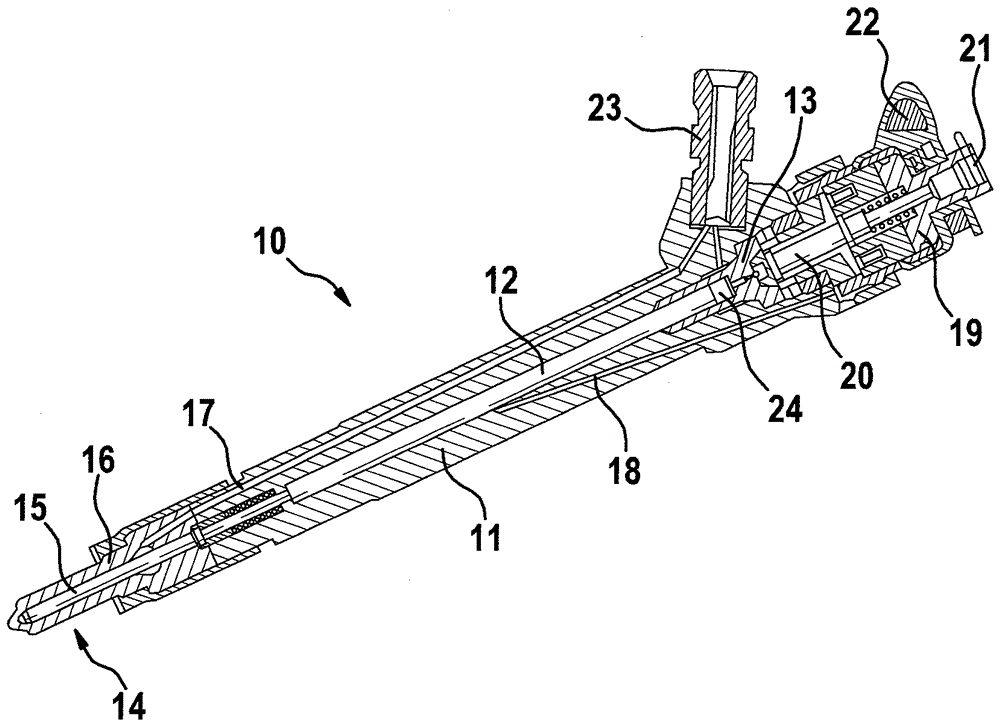
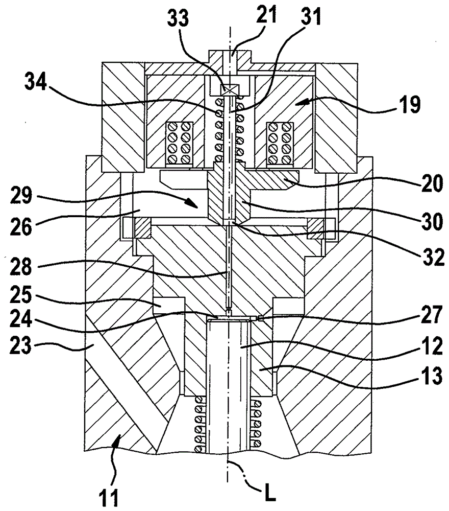
[0023] By means of the pair known in DE 10 2009 029 549 A1 and in figure 1 The adjustment of the fuel injector 10 shown in FIG. 1 illustrates one embodiment of the present invention. The fuel injector 10 comprises an injector body 11 in which a valve piston 12 is arranged. This valve piston is guided at the upper end within the valve part 13 . Its lower end extends in the direction of the nozzle 14 . The valve piston 12 is connected to a valve needle 15 of a needle valve 16 which is arranged inside the nozzle 14 . Furthermore, the valve piston 12 is connected to a high-pressure bore 17 and to a return bore 18 . Arranged at the upper end of the fuel injector 10 is a magnetic head 19 connected to the switching valve, an armature assembly 20 and a circuit 21 . Fuel injector 10 is also connected via an electrical connection 22 to an electrical energy source (not shown) and via a high-pressure connection 23 including a high-pressure slot filter to a fuel supply line (not shown)...


PUM


Abstract

The invention relates to a method for supplying current of a switching valve of a fuel injector. This includes energizing the switching valve to a predetermined current profile, determining a the pressure curve representing in a valve chamber of the fuel injector signal (U_NCS) during switching of the switching valve, and changing the predetermined current profile as a function of the signal (U_NCS).

Description

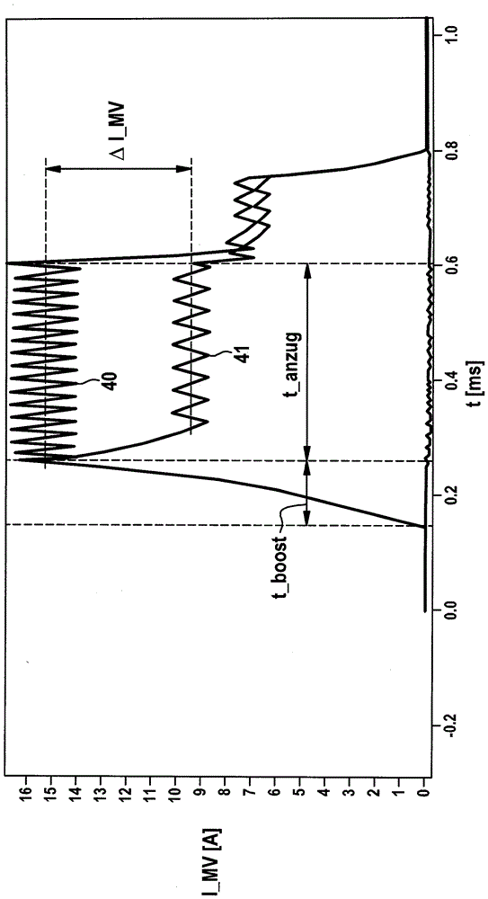
technical field [0001] The invention relates to a method for energizing a solenoid valve of a fuel injector. Furthermore, the invention relates to a computer program, which is configured to carry out the individual steps of the method according to the invention, and to a machine-readable storage medium, on which the computer program according to the invention is stored. Finally, the invention relates to an electronic control unit, which is provided for energizing a solenoid valve of a fuel injector by means of the method according to the invention. Background technique [0002] In order to open the internally open magnetic high-pressure injection valve in a device for direct fuel injection, a boost phase is required due to the high system pressure, during which the current through the fuel injector rises to about 16 amperes value. This serves to quickly provide an increased magnetic force in order to achieve a robust, reproducible opening of the switching valve of the fuel...

Claims


Application Information

Patent Timeline
Patent Type & Authority Applications(China)
IPC IPC(8): F02D41/20
CPCF02D41/20F02D2041/2017F02D2200/0602F02D2200/063F02M51/0639F02M63/0073F02M2200/247
Inventor R.科贝尔S.施泰因
Owner ROBERT BOSCH GMBH
Learn More