
A special attenuating wave generator for high-voltage equipment

A technology for high-voltage equipment and attenuating waves, applied in the field of attenuating wave generators dedicated to high-voltage equipment, can solve the problems of lack of attenuating signal generators, no custom functions, poor operability, etc., and achieve high application value and high operability. , The effect of making up the block diagram is concise

Active Publication Date: 2020-09-29
XISHUANGBANNA POWER SUPPLY BUREAU OF YUNNAN POWER GRID CO LTD
View PDF7 Cites 0 Cited by
  • Summary
  • Abstract
  • Description
  • Claims
  • Application Information

AI Technical Summary

Problems solved by technology

[0002] Since the country promotes the scientific research of enterprises and institutions, various researches on power grid equipment have developed rapidly. Adopting a highly flexible attenuation wave test source is conducive to the capture and simulation tests of various defects. State, has a very good practical significance, the existing attenuator is usually used to attenuate the signal gain, but the transition characteristics of the attenuation are not clearly required, such as after the output of the sine wave generator, after attenuation, the amplitude may be from 10V to 2V Attenuation, but this situation may be encountered in reality: it is necessary to provide a highly repetitive 10V to 2V attenuation transition waveform to observe the energy storage and oscillation characteristics of the device under test. For more in-depth research, it is necessary to analyze signals of different frequencies Attenuate and provide transition waveforms to observe the transition process of response signals at different frequencies. In precision electronic circuits, attenuation signal generators can have multiple control modes and output modes, but for high-voltage electrical equipment, devices in this field are relatively The main reason is that when analyzing transient characteristics, an integrated device with various transient waveforms and acquisitions is usually used, which mainly integrates various algorithms and acquisitions, so the equipment is bulky and lacks an independent attenuation signal generator. Moreover, the voltage during the test is small and the operability is poor, that is, for the delay of attenuation, voltage, symmetry, etc., only the transient characteristic analysis according to the standard can have automatic output and acquisition functions, and does not have custom functions

Method used


Image

  • A special attenuating wave generator for high-voltage equipment
  • A special attenuating wave generator for high-voltage equipment

Examples


Embodiment Construction

[0016] The following will clearly and completely describe the technical solutions in the embodiments of the present invention with reference to the accompanying drawings in the embodiments of the present invention. Obviously, the described embodiments are only some, not all, embodiments of the present invention. Based on the embodiments of the present invention, all other embodiments obtained by persons of ordinary skill in the art without making creative efforts belong to the protection scope of the present invention.

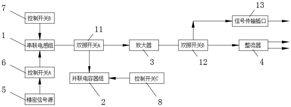
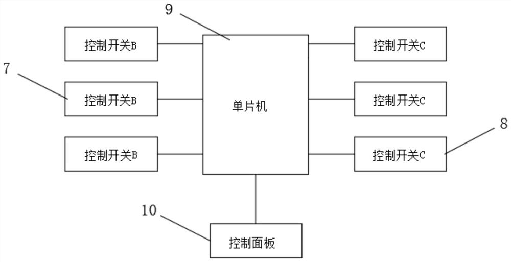
[0017] see Figure 1-2 As shown, in the embodiment of the present invention, an attenuated wave generator dedicated to high-voltage equipment includes a series inductor group 1, a parallel capacitor group 2, an amplifier 3, and a rectifier 4. The series inductor group 1 is electrically connected to a precision signal source 5, and the precision The output terminal of the signal source 5 is fixedly installed with a control switch A6, the control switch A6 is a ...


PUM


Abstract

The invention discloses an attenuation wave generator for a high-voltage device and belongs to the technical field of attenuation waves. The attenuation wave generator comprises a series inductor group, a parallel capacitor group, an amplifier and a rectifier. The series inductor group is electrically connected with a precision signal source. A control switch A is fixedly mounted on the output endof the precision signal source. The series inductor group is connected with a double-throw switch A through a wire. A plurality of control switches B are installed in the series inductor group. The two wiring terminals of the double-throw switch A are connected with the parallel capacitor group and the amplifier through wires respectively. By a control switch B and a control switch C, different inductance values can be obtained, and a process of increasing or decreasing the capacitance value of the parallel capacitor group can be realized. Therefore, the respective capacities and oscillationtime constants of LCs are changed, that is, a period of oscillation is adjusted. The control switch A can achieve the adjustment of an oscillation initial voltage amplitude and the control of oscillation attenuation duration.

Description

technical field [0001] The invention relates to an attenuating wave generator, in particular to a special attenuating wave generator for high-voltage equipment. Background technique [0002] Since the country promotes the scientific research of enterprises and institutions, various researches on power grid equipment have developed rapidly. Adopting a highly flexible attenuation wave test source is conducive to the capture and simulation tests of various defects. State, has a very good practical significance, the existing attenuator is usually used to attenuate the signal gain, but the transition characteristics of the attenuation are not clearly required, such as after the output of the sine wave generator, after attenuation, the amplitude may be from 10V to 2V Attenuation, but this situation may be encountered in reality: it is necessary to provide a highly repetitive 10V to 2V attenuation transition waveform to observe the energy storage and oscillation characteristics of ...

Claims


Application Information

Patent Timeline
Patent Type & Authority Patents(China)
IPC IPC(8): H02M7/04H02M5/06
CPCH02M5/06H02M7/043
Inventor 詹红生刘潇田军明方堃李胜马玉珠王浩兵赵霞陈勇慎王伟孙云川杨定光
Owner XISHUANGBANNA POWER SUPPLY BUREAU OF YUNNAN POWER GRID CO LTD
Learn More