Unlock instant, AI-driven research and patent intelligence for your innovation.

An electronic automatic drain

A technology of automatic drainage and drain, applied in the direction of machine/engine, liquid variable capacity machinery, pump control, etc., can solve the problems of non-drainage, air leakage, etc., and achieve the effect of solving easy blockage

Active Publication Date: 2018-04-06
BEIJING FENGDY S&T
View PDF11 Cites 0 Cited by
  • Summary
  • Abstract
  • Description
  • Claims
  • Application Information

AI Technical Summary

Problems solved by technology

[0005] In order to solve the phenomenon of air leakage and non-drainage in the existing condensate drainer, the invention provides a condensate (liquid) electronic automatic drainer

Method used


Image

  • An electronic automatic drain
  • An electronic automatic drain
  • An electronic automatic drain

Examples


Embodiment Construction

[0022] The present invention will be further described below in conjunction with the accompanying drawings and embodiments.

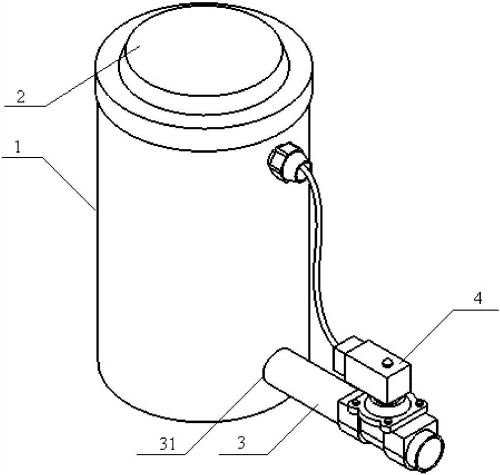
[0023] An electronic automatic drain, consisting of figure 1 , 2 , 3, including: a body 1 consisting of a side wall and a bottom, with an upper end opening, used to hold condensed water, a cover 2 that covers the opening of the body 1, and an inlet located on the upper part of the side wall of the body 1 The air port 5 is located at the drain port 31 at the lower part of the side wall of the body 1, and is located at the outside of the body 1, with one end connected to the drain pipe 3 of the drain port 31, and the solenoid valve 4 installed on the drain pipe 3 is fixed. The liquid level sensor 6 on the cover 2 is installed in the control circuit 8 in the cavity formed by the cover 2 . The control circuit 8 is connected with the liquid level sensor 6 and the solenoid valve 4 respectively. When the liquid level reaches the set upper limit or lower lim...


PUM


Abstract

The invention relates to an electronic automatic water draining device. The electronic automatic water draining device comprises a main body, a sealing cover, an air inlet, a water draining pipe, an electromagnetic valve, a liquid level sensor and a control circuit, wherein the main body consists of a side wall and a bottom, and is provided with an opening in the upper end; the sealing cover covers the opening of the main body; the air inlet is positioned in the upper part of the side wall of the main body; the water draining pipe is positioned outside the main body, and one end of the water draining pipe is connected with the lower part of the side wall of the main body; the electromagnetic valve is mounted on the water draining pipe; the liquid level sensor is fixed on the sealing cover; the control circuit is mounted in a cavity formed by the sealing cover; the control circuit is connected with the liquid level sensor and the electromagnetic valve. When a liquid level reaches an upper limit position or a lower limit position, which is set, the control circuit outputs a control signal to switch on or switch off the power supply of the electromagnetic valve, so that the water draining device can automatically start or stop draining water. A water draining opening is lower than the set lower limit position for draining water, so that the liquid level is always higher than the highest point of the water draining opening, and the problem of air leakage of a conventional water draining device is solved. Vane wheels at the bottom of the water draining device driven by water to rotate, dirt deposited at the bottom is stirred, and the dirt and the water are drained together, so that the problem that a water draining way is easy to block in the conventional water draining device is solved.

Description

technical field [0001] The invention belongs to the technical field of compressed air systems, and in particular relates to an electronic automatic drainer used for draining condensed water (liquid) in compressed air systems. Background technique [0002] The condensed water drain in the compressed air system is used to discharge the condensed water in the humid air, and ensure that the condensed water is discharged without causing the leakage of compressed air. At present, there are mainly two types of condensate drains on the market: mechanical and induction. These two types of drainers often have air leakage or no drainage during the actual application process. [0003] AD402 drainer is a commonly used mechanical drainer. When working, the condensed water enters the container from the inlet, the valve core is opened, and the air path communicates with the upper chamber of the diaphragm valve, so that the upper and lower chambers of the diaphragm valve are filled with pr...

Claims


Application Information

Patent Timeline
Patent Type & Authority Patents(China)
IPC IPC(8): F04B39/00F04B49/06F04B49/22
CPCF04B39/00F04B49/06F04B49/22
Inventor 田其宇张金峰王志新
Owner BEIJING FENGDY S&T