Moisture-proof drainage system for prefabricated substation and using method thereof
A prefabricated substation and drainage system technology, which is applied in distribution substations, substation/distribution device enclosures, substation/switch layout details, etc., can solve the problem of water droplets easily adhering to electrical equipment, high humidity in the box, and pre-installation The installed substation does not have problems such as moisture-proof drainage system, so as to achieve the effect of automatic drainage and convenient heat dissipation
- Summary
- Abstract
- Description
- Claims
- Application Information
AI Technical Summary
Problems solved by technology
Method used
Image
Examples
Embodiment 1
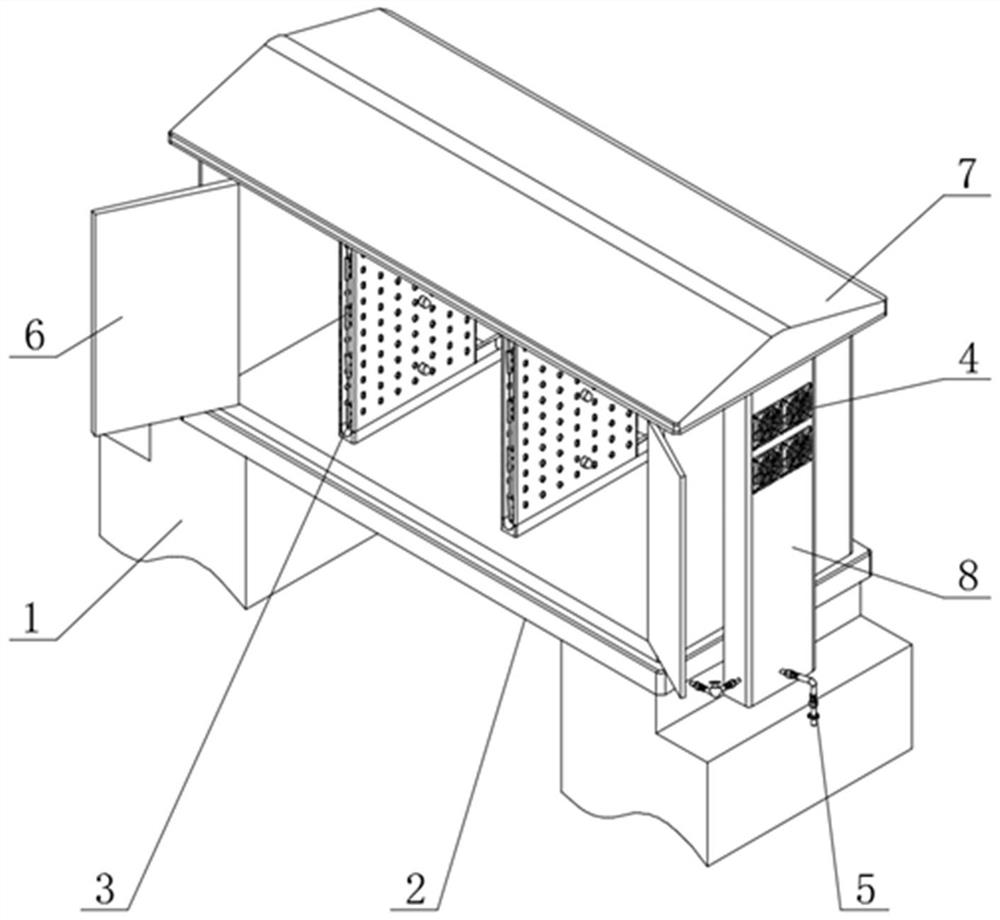
[0030] see Figure 1-8 , the present invention provides a technical solution:
[0031] A moisture-proof drainage system for a prefabricated substation, comprising a foundation pit base 1, a cabinet body 2, a condensation device 3, a circulation device 4 and a drainage device 5, the upper end of the foundation pit base 1 is fixedly connected with a cabinet body 2, and the cabinet body 2 The front end is rotationally connected with a cabinet door 6, the upper end of the cabinet body 2 is fixedly connected with a rainproof ceiling 7, the right end of the cabinet body 2 is fixedly connected with a side installation tube 8, and the side installation tube 8 lower end is fixedly connected with the foundation pit base 1.
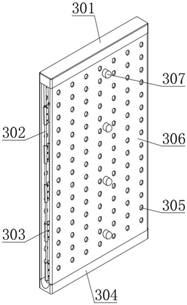
[0032] The interior of the cabinet 2 is fixedly connected with a condensing device 3. The condensing device 3 includes a water-permeable plate 301, a cooling pipe 302, a pipe clamp 303 and a sump 304. The lower end of the sump 304 is fixedly connected with the cabin...
Embodiment 2
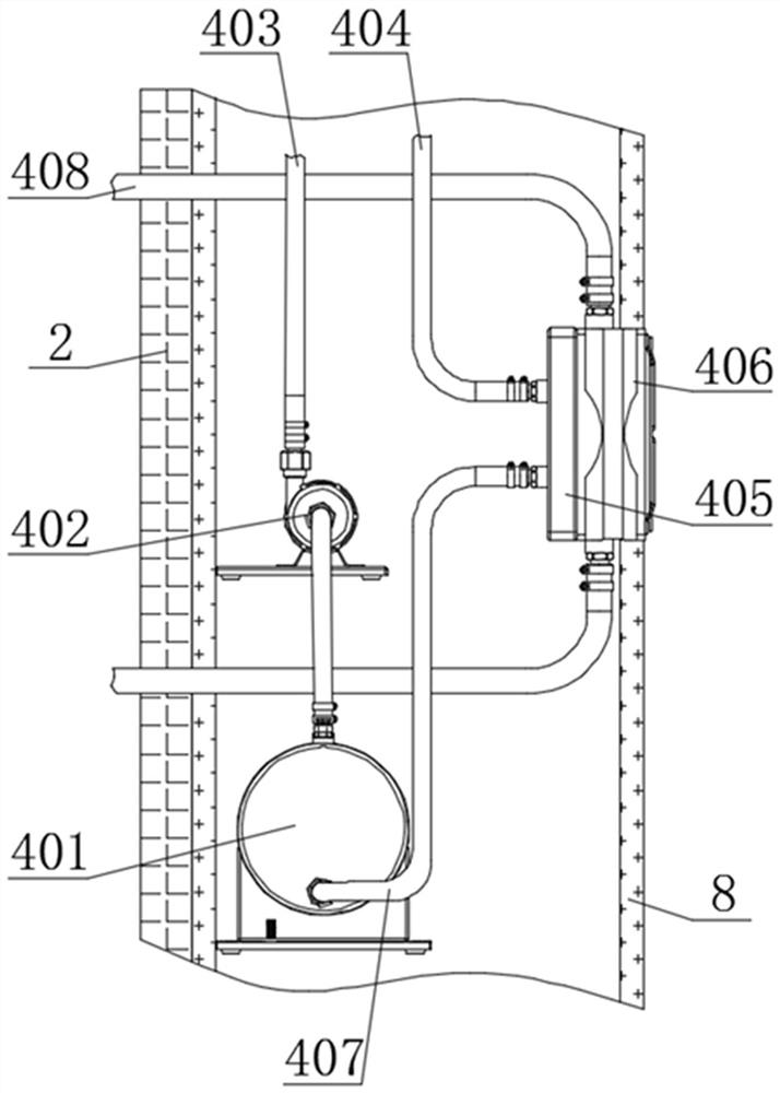
[0035] see figure 1 , image 3 , Figure 4 , the present invention provides a technical solution:
[0036] A moisture-proof drainage system for a prefabricated substation, comprising a foundation pit base 1, a cabinet body 2, a condensation device 3, a circulation device 4 and a drainage device 5, the upper end of the foundation pit base 1 is fixedly connected with a cabinet body 2, and the cabinet body 2 The front end is rotationally connected with a cabinet door 6, the upper end of the cabinet body 2 is fixedly connected with a rainproof ceiling 7, the right end of the cabinet body 2 is fixedly connected with a side installation tube 8, and the side installation tube 8 lower end is fixedly connected with the foundation pit base 1.
[0037] The interior of the cabinet 2 is fixedly connected with a condensing device 3. The condensing device 3 includes a water-permeable plate 301, a cooling pipe 302, a pipe clamp 303 and a sump 304. The lower end of the sump 304 is fixedly co...
PUM
 Abstract
Description
Claims
Application Information
 - R&D
- Intellectual Property
- Life Sciences
- Materials
- Tech Scout
- Unparalleled Data Quality
- Higher Quality Content
- 60% Fewer Hallucinations
Browse by: Latest US Patents, China's latest patents, Technical Efficacy Thesaurus, Application Domain, Technology Topic, Popular Technical Reports.
© 2025 PatSnap. All rights reserved.Legal|Privacy policy|Modern Slavery Act Transparency Statement|Sitemap|About US| Contact US: help@patsnap.com


