A Multi-level Redundant Main Shaft Sealing Method
A main shaft sealing and redundant technology, which is applied in the direction of engine sealing, engine components, mechanical equipment, etc., can solve the problems of abnormal and stable operation of the motor, leakage of thin motor oil, and easy damage of the seal, so as to ensure long-term stable operation , Increase sealing reliability and prevent damage
- Summary
- Abstract
- Description
- Claims
- Application Information
AI Technical Summary
Problems solved by technology
Method used
Image
Examples
Embodiment 1
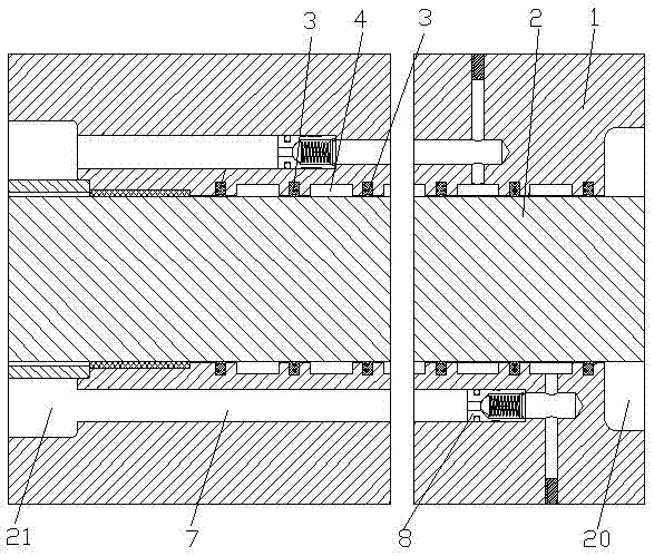
[0042] see figure 1 , a multi-stage redundant main shaft sealing method, the main shaft 2 is provided with a seal seat 1 in contact with the external medium chamber 20, an axial hole 7 is opened in the seal seat 1, and the axial hole 7 communicates with the internal oil chamber 21; Install a one-way valve 8 in the axial hole 7, insert a sealing ring 3 in the sealing seat 1 to form an annular transition chamber 4; connect the annular transition chamber 4 and the axial hole 7, and pass through the one-way valve 8 in the axial hole 7 Move axially to adjust the pressure difference between the annular transition chamber 4 and the inner oil chamber 21 .
[0043] This embodiment is the most basic implementation. A seal seat in contact with the external medium chamber is arranged on the main shaft, and an axial hole is opened in the seal seat, and the axial hole communicates with the internal oil chamber; a check valve is installed in the axial hole. , a sealing ring is embedded in t...
Embodiment 2
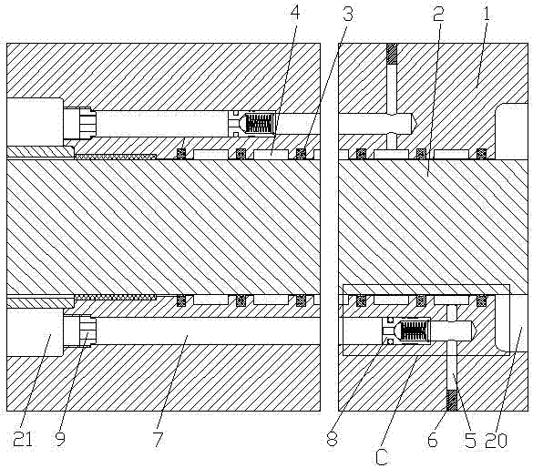
[0045] see figure 2 and image 3 , a multi-stage redundant main shaft sealing method, the main shaft 2 is provided with a seal seat 1 in contact with the external medium chamber 20, an axial hole 7 is opened in the seal seat 1, and the axial hole 7 communicates with the internal oil chamber 21; Install a one-way valve 8 in the axial hole 7, insert a sealing ring 3 in the sealing seat 1 to form an annular transition chamber 4; connect the annular transition chamber 4 and the axial hole 7, and pass through the one-way valve 8 in the axial hole 7 Move axially to adjust the pressure difference between the annular transition chamber 4 and the inner oil chamber 21 .
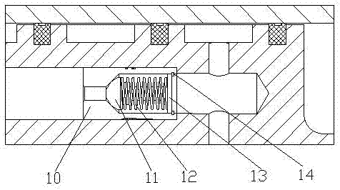
[0046] At least two sealing rings 3 are embedded in the sealing seat 1, an annular transition cavity 4 is formed between the sealing seat 1, the main shaft 2 and two adjacent sealing rings 3, the annular transition cavity 4 is filled with grease, and the annular transition There is a radial hole 5 on the cavity 4, a...
Embodiment 3
[0051] see Figure 4 and Figure 5 , a multi-stage redundant main shaft sealing method, the main shaft 2 is provided with a seal seat 1 in contact with the external medium chamber 20, an axial hole 7 is opened in the seal seat 1, and the axial hole 7 communicates with the internal oil chamber 21; Install a one-way valve 8 in the axial hole 7, insert a sealing ring 3 in the sealing seat 1 to form an annular transition chamber 4; connect the annular transition chamber 4 and the axial hole 7, and pass through the one-way valve 8 in the axial hole 7 Move axially to adjust the pressure difference between the annular transition chamber 4 and the inner oil chamber 21 .
[0052] At least two sealing rings 3 are embedded in the sealing seat 1, an annular transition cavity 4 is formed between the sealing seat 1, the main shaft 2 and two adjacent sealing rings 3, the annular transition cavity 4 is filled with grease, and the annular transition There is a radial hole 5 on the cavity 4, ...
PUM
 Abstract
Description
Claims
Application Information
 - R&D
- Intellectual Property
- Life Sciences
- Materials
- Tech Scout
- Unparalleled Data Quality
- Higher Quality Content
- 60% Fewer Hallucinations
Browse by: Latest US Patents, China's latest patents, Technical Efficacy Thesaurus, Application Domain, Technology Topic, Popular Technical Reports.
© 2025 PatSnap. All rights reserved.Legal|Privacy policy|Modern Slavery Act Transparency Statement|Sitemap|About US| Contact US: help@patsnap.com


