A double-tension-source type yield stress measuring system for a magnetorheological fluid

A magnetorheological fluid and yield stress technology, applied in the field of magnetorheological fluid performance research, can solve problems such as different data, and achieve the effect of convenient operation, easy observation, and accurate yield stress value.

Active Publication Date: 2016-05-04
SHANGHAI UNIV OF ENG SCI
View PDF6 Cites 5 Cited by
  • Summary
  • Abstract
  • Description
  • Claims
  • Application Information

AI Technical Summary

Problems solved by technology

These test methods are based on different theoretical models and test methods, resulting in different data obtained by using different test methods to measure the same magnetorheological fluid sample

Method used


Image

  • A double-tension-source type yield stress measuring system for a magnetorheological fluid
  • A double-tension-source type yield stress measuring system for a magnetorheological fluid
  • A double-tension-source type yield stress measuring system for a magnetorheological fluid

Examples


Embodiment 1

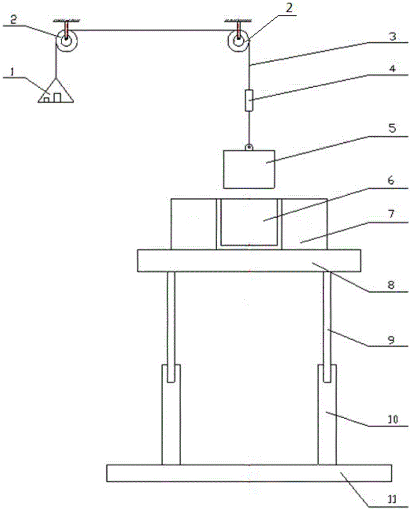
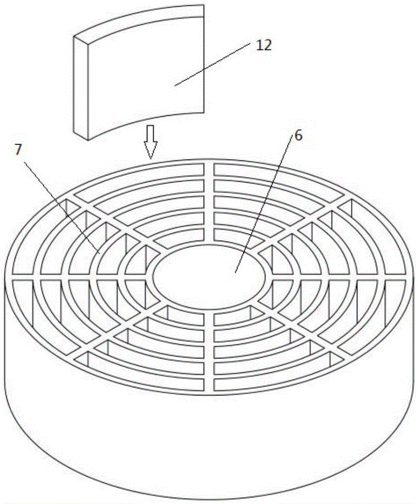
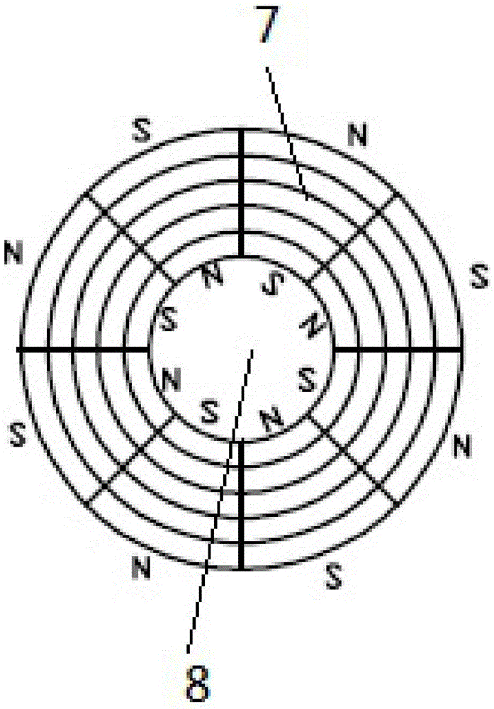
[0042] A dual tension source magnetorheological fluid yield stress measurement system, such as figure 1 As shown, it includes a lifting device, a magnetic field generating device and a lifting block 5. Magnetic field generators such as Figure 2~3 As shown, it is composed of a radial multi-stage magnetic ring and a magneto-rheological fluid tank 6. The radial multi-stage magnetic ring is composed of a plurality of radial multi-stage magnetic ring units coaxially arranged in a plane, and the radial multi-stage magnetic ring The ring unit is in the shape of a ring and is surrounded by a plurality of arc-shaped permanent magnets 12. The arc-shaped permanent magnets 12 are placed in the permanent magnet grid groove 7, and the permanent magnet grid groove 7 is fixed on the flat plate 8. The number of multi-stage magnetic ring units is used to change the magnitude of the magnetic field strength. The magnetorheological fluid tank 6 is cylindrical, located in the radial multi-stage ...

Embodiment 2

[0045] This embodiment is basically the same as the embodiment, except that the side of the pull block 5 in this embodiment is provided with a plurality of toothed grooves arranged along the axial direction of the pull block 5 around its side, such as Figure 7-8 As shown, the toothed groove has a width of 2 mm and a depth of 1 mm. The method for measuring the yield stress of the magnetorheological fluid is similar to that of Example 1.

Embodiment 3

[0047]A kind of dual tension source type magnetorheological fluid yield stress measurement system of this embodiment is basically the same as that of Embodiment 1, the difference is that the method of measuring the yield stress of magnetorheological fluid in this embodiment is to lift the block 5. After inserting into the magnetorheological fluid, fix the pull rope 3 on the fixed pulley 2 so that it does not move, start the lifting device, make it descend slowly at a constant speed, and generate a relative pulling force on the lifting block 5, and the pulling force is measured by the pulling force sensor 4 size, the yield stress of the magnetorheological fluid can be converted.


PUM


Abstract

The invention relates to a double-tension-source type yield stress measuring system for a magnetorheological fluid. The system comprises a lifting device, a magnetic field generating device and a lifting block. The magnetic field generating device comprises a radial multi-stage magnetic ring and a magnetorheological fluid tank. The magnetorheological fluid tank is cylindrical and is disposed in the radial multi-stage magnetic ring. The magnetorheological fluid tank and the radial multi-stage magnetic ring are coaxially arranged. The magnetic field generating device is arranged horizontally. The bottom of the magnetic field generating device is provided with the lifting device. The lifting block is in a cylinder shape. The outer diameter of the lifting block is smaller than the inner diameter of the magnetorheological fluid tank. The lifting block and the magnetorheological fluid tank are coaxially arranged. The lifting block is pulled by a pulling rope to move along the straight line where the axis of the magnetorheological fluid tank is. The pulling rope is provided with a tension sensor. Compared with the prior art, the system is advantaged by accurate measurement results, visual data presentation, and the like.

Description

technical field [0001] The invention relates to the field of research on the properties of magnetorheological fluids, in particular to a device for measuring the yield stress of magnetorheological fluids with dual tension sources. Background technique [0002] Magnetorheological fluid (MRF) is a material whose rheological properties change drastically under the action of an external magnetic field. It behaves as a Newtonian fluid with good flow when there is no external magnetic field; but under the action of an external strong magnetic field, its apparent viscosity can be changed. It increases by several orders of magnitude within milliseconds, and exhibits solid-like mechanical properties, and the viscosity change is continuously reversible, that is, once the magnetic field is removed, it becomes a flowable liquid again. Using the characteristics of magnetorheological fluid, the purpose of changing the dynamic characteristics of the system can be achieved by adjusting the ...

Claims


Application Information

Patent Timeline
Patent Type & Authority Applications(China)
IPC IPC(8): G01N11/10
CPCG01N11/10G01N2011/0033
Inventor 邵俊罗一平任洪娟康路路孙玉香
Owner SHANGHAI UNIV OF ENG SCI
Why Eureka
Try Eureka