
Vertical measurement ionogram reversion method based on overlapping polynomial model

A technology of overlapping polynomials and ionograms, which is applied in the reflection/re-radiation of radio waves, measurement devices, radio wave measurement systems, etc., and can solve the problems of large influence on data quality accuracy, increase of profile calculation errors, and wrong interpolation results.

Active Publication Date: 2016-05-04
THE 22ND RES INST OF CHINA ELECTRONICS TECH GROUP CORP
View PDF5 Cites 4 Cited by
  • Summary
  • Abstract
  • Description
  • Claims
  • Application Information

AI Technical Summary

Problems solved by technology

The disadvantage of this method is that it is directly based on the actual detection data, so the quality of the data has a great impact on its accuracy. A small amount of false high data missing will directly cause the calculation profile to oscillate, and a large amount of data missing will cause a large deformation of the profile and Due to the fading of the detection equipment and the ionosphere, the lack of actual detection data of false heights is inevitable; moreover, some direct interpolation methods for detection data of false heights do not combine the propagation characteristics of the ionosphere, and the A small amount of missing data near the adjacent frequency can play a better interpolation, but for more or a large number of missing data and data missing near the adjacent frequency of each layer, it may get completely wrong interpolation results, which further increases the calculation error of the profile
In addition, the "valley" in the ionospheric profile is not specifically involved in this method, but it is not in line with the actual situation in the physical sense

Method used


Image

  • Vertical measurement ionogram reversion method based on overlapping polynomial model
  • Vertical measurement ionogram reversion method based on overlapping polynomial model
  • Vertical measurement ionogram reversion method based on overlapping polynomial model

Examples


Embodiment 1

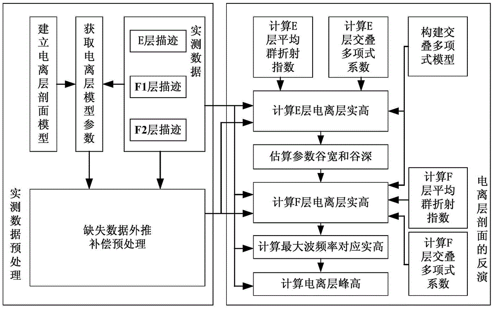
[0119] Example 1, such as figure 1 As shown, this embodiment discloses a vertical ionogram inversion method based on an overlapping polynomial model, and the method includes the following steps:

[0120] (1) Construct a mathematical model of the ionospheric profile:

[0121] The present invention models the ionosphere as including the E layer, valley layer, layer, The four-layer model of layer E, the profile of E layer and the valley layer is parabolic, layers and The layer profile is of polynomial type. In order to make the established electron concentration profile meet the continuous smooth characteristic, at the connection point between layers, the plasma frequency (square) value and profile gradient calculated based on the ionospheric model above and below the connection point respectively should be equal, according to this condition , defining the intrinsic relationship between the relevant parameters.

[0122] (2) Obtain the parameters for constructing the ionos...


PUM


Abstract

The invention discloses a vertical measurement ionogram reversion method based on an overlapping polynomial model. The method comprises the following steps: step A, preprocessing actually measured data; step B, based on a result of the preprocessing of the actually measured data, calculating an E-layer profile by use of the overlapping polynomial model; step C, based on the actually measured data preprocessing result and the E-layer profile, estimating a parameter valley width Wv and a valley depth Fv, and constructing corresponding valley layer parameter profiles; and step D, based on the actually measured data preprocessing result and the valley layer profiles, calculating an F-layer profile by use of the overlapping polynomial model. According to the vertical measurement ionogram reversion method based on the overlapping polynomial model, disclosed by the invention, a vertical measurement ionogram reversion method which is based on an overlapping polynomial model idea and is integrated with data preprocessing and valley layer profile searching optimization is brought forward, and the ionosphere inversion precision and stability can be effectively improved.

Description

technical field [0001] The invention relates to the field of ionosphere research and application, in particular to a vertical ionogram inversion method based on an overlapping polynomial model. Background technique [0002] Ionospheric vertical detection (referred to as vertical detection) technology is the earliest detection method used in the history of ionospheric research. Although there are many detection technologies, ionospheric vertical detection technology is still the most important ionospheric detection method. The vertical ionogram reflecting the relationship between the false height of the ionosphere and the frequency can be obtained through the vertical detection of the ionosphere. The false height obtained by the vertical survey is not the real reflection height of electromagnetic waves in the ionosphere, and the acquisition of the real reflection height requires the inversion of the vertical survey ionogram. Correspondence between ionosphere height and plasm...

Claims


Application Information

Patent Timeline
Patent Type & Authority Applications(China)
IPC IPC(8): G01S13/89
CPCG01S13/89
Inventor 鲁转侠柳文蔚娜杨龙泉冯静郭文玲师燕娥
Owner THE 22ND RES INST OF CHINA ELECTRONICS TECH GROUP CORP
Learn More