Iris identification device and control method thereof

A technology of iris recognition and control method, applied in the field of biometrics, which can solve the problems of high image quality requirements for iris recognition, inability to adapt to everyone's use, and poor user experience, etc., to achieve simple and intelligent control methods, improve user experience and friendliness Sexuality, simple and intelligent control process

Active Publication Date: 2016-05-04
BEIJING TECHSHINO TECH
View PDF6 Cites 3 Cited by
  • Summary
  • Abstract
  • Description
  • Claims
  • Application Information

AI Technical Summary

Problems solved by technology

However, the current biometric identification devices are installed at a fixed position and fixed at a certain height. Due to differences in the height of different users, the installation method of this fixed device cannot adapt to everyone's use.
Especially for iris recognition devices, because iris recognition mainly collects images of the user's eyes for recognition, the collection range is small, and iris recognition has high requirements for image quality, and its collection distance range is also narrow. Therefore, the fixed installation method can only To meet the needs of users of some heights, for users of other heights, a high degree of cooperation is required to complete the identification. For example, if the installation position of the iris recognition device is low, it is more convenient for shorter users, but taller users Users need to bend their knees or bend down to make the iris position parallel to the device. If the installation position is higher, it will be more convenient for taller users, but for shorter users, it may be necessary to raise their feet or other methods to make the iris position parallel to the device
Therefore, the fixed installation method of the iris recognition device makes the user experience poor and the user friendliness is low

Method used


Image

  • Iris identification device and control method thereof
  • Iris identification device and control method thereof
  • Iris identification device and control method thereof

Examples


Embodiment 1

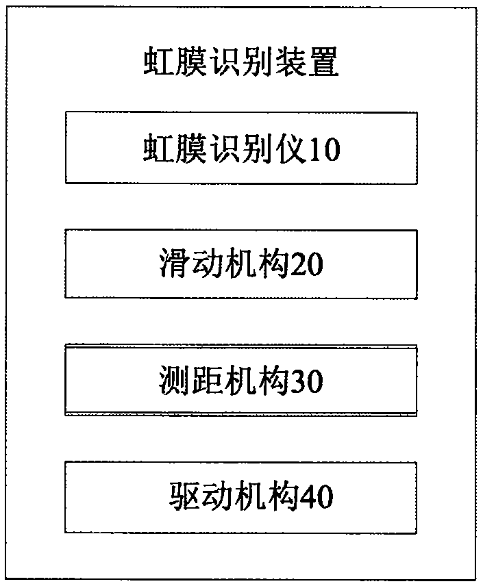
[0037] Such as figure 2 Shown: iris recognition device comprises iris recognition instrument 1, sliding mechanism 2, distance measuring mechanism 3 and driving mechanism 4, and wherein iris recognition instrument 1 comprises a control processor ( figure 2 not shown in ), the initial position is set at the lower limit position of the sliding mechanism, the sliding mechanism 2 includes two parallel and vertically arranged slideways (21 / 22), the ranging mechanism 3 includes a first ranging module 31, which is arranged on the iris The bottom middle position of the recognition instrument, the driving mechanism 4 is arranged on the back of the iris recognition instrument ( figure 2 shown in dotted line). The iris recognition device also includes a position-limiting mechanism 5, and the position-limiting mechanism comprises two position-limiting plates and two photoelectric induction sensors ( figure 2 Middle dotted line shows), wherein a limiting plate 51 is positioned at the ...

Embodiment 2

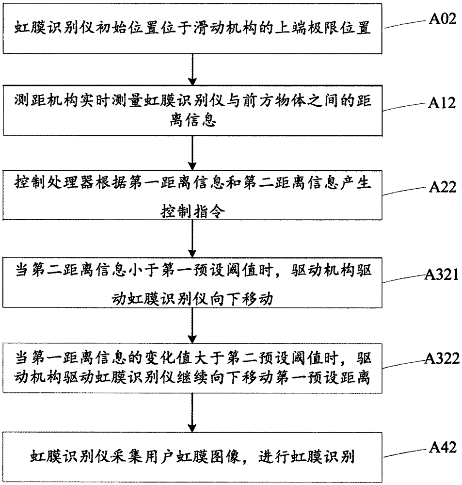
[0040] Such as image 3 Shown: iris recognition device comprises iris recognition instrument 1 ', sliding mechanism 2 ', distance measuring mechanism 3 ' and driving mechanism 4 ', wherein iris recognition instrument 1 ' comprises a control processor ( image 3 (not shown in )) the initial position is set at the upper limit position of the sliding mechanism, the sliding mechanism 2' includes two parallel and vertical slideways (21' / 22'), the ranging mechanism 3' includes two ranging modules, the second A distance measuring module 31 is arranged at the bottom middle position of the iris recognition instrument, the second distance measuring module 32' is arranged at the bottom middle position of the slide mechanism, and the drive mechanism 4' is arranged at the back of the iris recognition instrument ( image 3 shown in dotted line). The iris recognition device also includes an infrared generator 61' and an infrared receiver 62'. The infrared generator is arranged on the slidin...

Embodiment 3

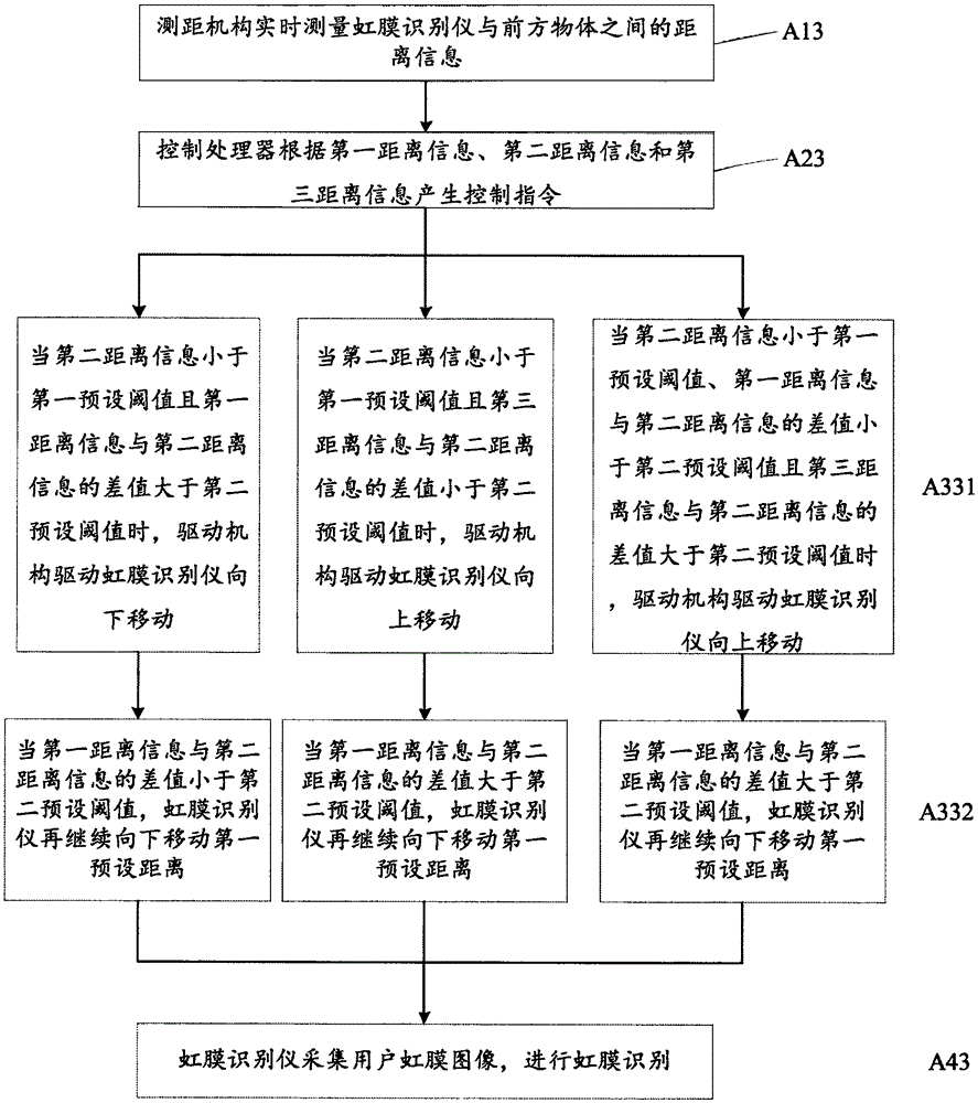
[0045] Such as Image 6 Shown: iris recognition device comprises iris recognition instrument 1 ", sliding mechanism 2 ", distance measuring mechanism 3 " and driving mechanism 4 ", and wherein iris recognition instrument 1 " comprises a control processor ( Image 6 not shown in ), the sliding mechanism 2" includes two parallel and vertical slideways (21" / 22"), the ranging mechanism 3" includes three ranging modules, and the first ranging module 31" is arranged on the iris recognition The middle position of the bottom of the iris recognition instrument, the second distance measuring module 32" is set at the bottom middle position of the sliding mechanism, the third distance measuring module 33" is set at the top middle position of the iris recognition instrument, and the driving mechanism 4" is set at the back of the iris recognition instrument ( Image 6 shown in dotted line). The iris recognition device also includes a limit mechanism 5 ", and the limit mechanism includes t...


PUM


Abstract

The present invention discloses an Iris identification device and a control method thereof, belonging to the field of the biometric identification. The device provided by the invention comprises: an iris identification instrument, a sliding mechanism, a distance measurement mechanism and a driving mechanism. The control method comprises: the distance measurement mechanism is configured to measure the distance information between the iris identification instrument and an object at the front; the control processor of the iris identification instrument is configured to generate control instructions according to the distance information; the driving mechanism is configured to drive the iris identification instrument to move relative to the sliding mechanism according to the control instructions; and the iris identification instrument is configured to collect user iris images and perform iris identification. The iris identification device and control method thereof are able to be suitable for users in different heights, and have more intelligent identification process, good user experience and high friendliness.

Description

technical field [0001] The invention relates to the field of biological identification, in particular to an iris identification device and a control method. Background technique [0002] With the development of biometric technology, traditional identification devices such as ID / IC card recognition devices are gradually replaced by biometric devices, first replaced by fingerprint recognition devices, and now gradually replaced by face recognition devices and iris with higher security levels. Identification device replacement. However, the installation positions of the current biometric identification devices are all fixed, and they are fixedly installed at a certain height. Because there are differences in the heights of different users, the installation method of this fixed device cannot be adapted to everyone's use. Especially for iris recognition devices, because iris recognition mainly collects images of the user's eyes for recognition, the collection range is small, and...

Claims


Application Information

Patent Timeline
IPC IPC(8): G06K9/00G05D3/12
CPCG05D3/12G06V40/19
Inventor 周涛
Owner BEIJING TECHSHINO TECH
Why Eureka
Try Eureka