Motor rotor position detection method and device

A technology of motor rotor and rotor angle, applied in the direction of electronic commutator, etc., can solve the problem of high cost and achieve the effect of reducing cost

Active Publication Date: 2016-05-04
CHERY AUTOMOBILE CO LTD
View PDF4 Cites 20 Cited by
  • Summary
  • Abstract
  • Description
  • Claims
  • Application Information

AI Technical Summary

Problems solved by technology

[0005] In order to solve the problem of high cost of detecting the rotor position of a permanent magnet synchronous motor usi

Method used


Image

  • Motor rotor position detection method and device
  • Motor rotor position detection method and device
  • Motor rotor position detection method and device

Examples


Embodiment Construction

[0064] In order to make the object, technical solution and advantages of the present invention clearer, the implementation manner of the present invention will be further described in detail below in conjunction with the accompanying drawings.

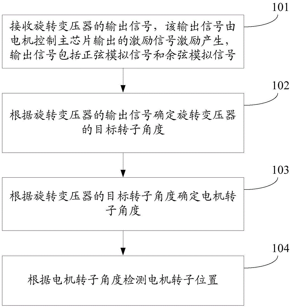
[0065] The embodiment of the present invention provides a motor rotor position detection method for the motor control main chip, such as figure 1 As shown, the method may include:

[0066] Step 101: Receive the output signal of the resolver, the output signal is generated by the excitation signal output by the motor control main chip, and the output signal includes a sine analog signal and a cosine analog signal.

[0067] Step 102. Determine the target rotor angle of the resolver according to the output signal of the resolver.

[0068] Step 103. Determine the rotor angle of the motor according to the target rotor angle of the resolver.

[0069] Step 104, detecting the position of the rotor of the motor according to the rotor angle of...


PUM


Abstract

The invention discloses a motor rotor position detection method and device and belongs to the technical field of driving control. The method is used for a motor control main chip and comprises the steps of: receiving output signals of a rotary transformer, wherein the output signals are excited by excitation signals output by the motor control main chip and comprise sine analog signals and cosine analog signals; determining a target rotor angle of the rotary transformer according to the output signals of the rotary transformer; determining a motor rotor angle according to the target rotor angle of the rotary transformer; and detecting the position of the motor rotor according to the motor rotor angle. The motor rotor position detection method and device solve the problem in the prior art that the cost is relatively high when the rotary transformer is utilized to detect the position of the permanent magnet synchronous motor rotor, the cost of permanent magnet synchronous motor rotor position detection is lowered, and the motor rotor position detection method and device can be used to detect the position of the permanent magnet synchronous motor rotor.

Description

technical field [0001] The invention relates to the technical field of drive control, in particular to a method and device for detecting the position of a motor rotor. Background technique [0002] The permanent magnet synchronous motor is an environmentally friendly and low-carbon motor with high energy density. The permanent magnet synchronous motor mainly includes a motor stator, a motor rotor, a motor control main chip, and an electronic reversing switch. In recent years, permanent magnet synchronous motors have been widely used in pure electric vehicles. In order to ensure the stable and reliable operation of permanent magnet synchronous motors, it is necessary to detect the rotor position of permanent magnet synchronous motors. A position sensor is installed on the synchronous motor, and the purpose of detecting the rotor position of the permanent magnet synchronous motor is achieved by calculating the angle of the position sensor. The position sensor may be a Hall se...

Claims


Application Information

Patent Timeline
IPC IPC(8): H02P6/16
CPCH02P6/16
Inventor 陈立冲蔡交明王瑛钱兆刚
Owner CHERY AUTOMOBILE CO LTD
Why Eureka
Try Eureka