Radiant heat pad and method for manufacturing the same

A manufacturing method and technology of heat dissipation pad, which are applied in cooling/ventilation/heating transformation, housing with display/control unit, electrical components, etc., which can solve the problem of occupation, thickening of liquid crystal display device thickness, and difficulty in heat dissipation design of internal components, etc. question

Inactive Publication Date: 2016-05-04
GSR COMPANY
View PDF5 Cites 2 Cited by
  • Summary
  • Abstract
  • Description
  • Claims
  • Application Information

AI Technical Summary

Problems solved by technology

However, in prior art 2, in order to dissipate the heat generated by the light source, an aluminum plate-shaped bottom cover is used, so the heat dissipation design based on internal components is not only difficult, but also takes up a large design space, making liquid crystal display devices (television sets) ) becomes thicker, and the bottom cover is formed of an aluminum plate with a set thickness, so the production unit price is high, reducing price competitiveness

Method used


Image

  • Radiant heat pad and method for manufacturing the same
  • Radiant heat pad and method for manufacturing the same
  • Radiant heat pad and method for manufacturing the same

Examples


Embodiment Construction

[0019] Hereinafter, embodiments of the heat dissipation pad and its manufacturing method of the present invention will be described with reference to the accompanying drawings.

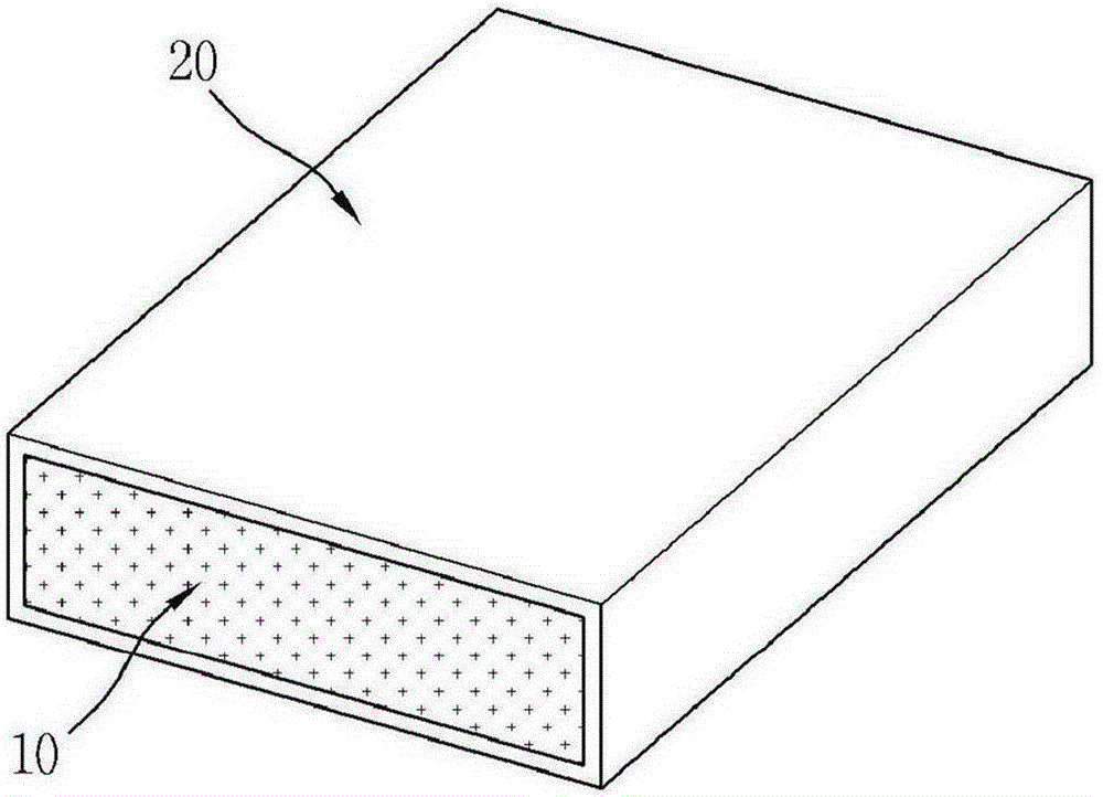
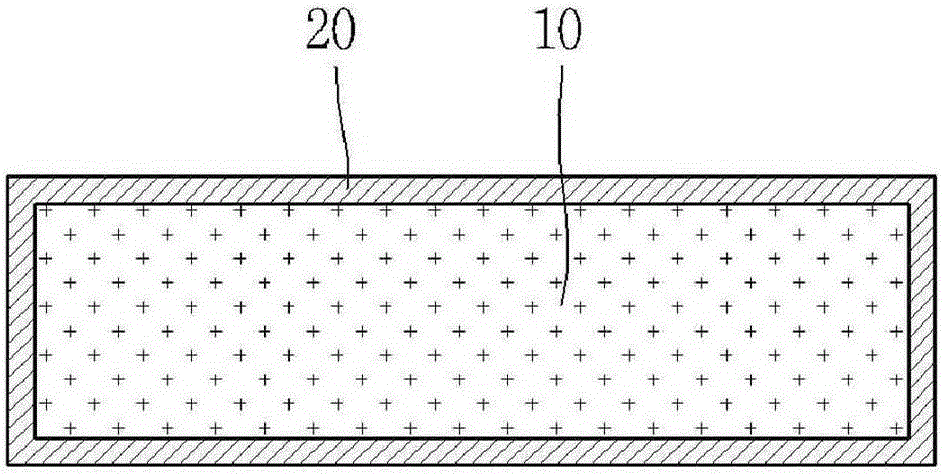
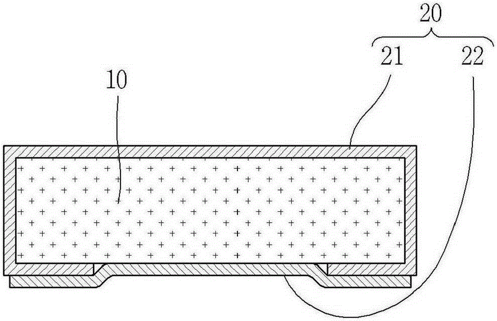
[0020] figure 1 It is a perspective view showing an embodiment of the heat dissipation pad of the present invention. figure 2 It is a sectional view showing an embodiment of the heat dissipation pad of the present invention.

[0021] Such as figure 1 , 2 As shown, an embodiment of the heat dissipation pad of the present invention includes a base member 10 and a heat dissipation film 20 .

[0022] Preferably, the base member 10 is made of an elastic material that contracts when pressed and recovers after being released. More preferably, the base member 10 is a porous material having elastic force and having a plurality of holes inside to allow air to flow. As an example of the base member 10, the base member 10 is preferably made of a sponge material. The base member 10 is preferably formed in a...


PUM


Abstract

The present invention relates to a heat radiation pad and a manufacturing method thereof. The present invention includes a base member with elasticity and a heat radiation thin film which surrounds the base member and includes a metal element. The present invention includes the steps of: forming the base member of a bar shape with elasticity; forming an adhesion layer on one side of the heat radiation thin film; and surrounds the base member with the heat radiation thin film to bone the adhesion layer to the base member. The present invention quickly discharges heat from a heating component to the outside and reduces manufacturing costs. Also, a heat radiation design is easily made by high application.

Description

technical field [0001] The invention relates to a cooling pad and a manufacturing method thereof. Background technique [0002] Generally speaking, plasma display panels (Plasma Display Panel, PDP) and liquid crystal display panels (Liquid Crystal Display Panel) not only have a large screen, but also have high resolution and thin thickness, so they are used as display panels for large televisions. Liquid crystal display panels are also used as display panels for computer monitors. [0003] A plasma display panel is an image display device that arranges at least two discharge electrodes, ie, a positive electrode and a negative electrode, in a discharge space filled with gas, and utilizes gas plasma discharge. As we all know, in a PDP that uses three electrodes, that is, a sustain electrode, a conduction / sustain electrode, an address electrode, and a fluorescent substance, to display a video signal, a non-interlaced scan (Non-interlaced scan) is used to display a frame for ea...

Claims


Application Information

Patent Timeline
Patent Type & Authority Applications(China)
IPC IPC(8): H05K7/20
CPCH05K5/0017H05K7/20472H05K7/20963
Inventor 崔相文
Owner GSR COMPANY
Why Eureka
Try Eureka