Method for determining the distance and relative speed of a remote object

A relative speed and object technology, applied in the direction of using re-radiation, radio wave reflection/re-radiation, measuring devices, etc., can solve the problems of analysis and processing cost, cost, and significant

Active Publication Date: 2016-05-04
S M S SMART MICROWAVE SENSORS
View PDF4 Cites 3 Cited by
  • Summary
  • Abstract
  • Description
  • Claims
  • Application Information

AI Technical Summary

Problems solved by technology

Therefore, analysis processing costs are significant and require not only efficient algorithms but also fast computational performance
Furthermo...

Method used


Image

  • Method for determining the distance and relative speed of a remote object
  • Method for determining the distance and relative speed of a remote object
  • Method for determining the distance and relative speed of a remote object

Examples


Embodiment Construction

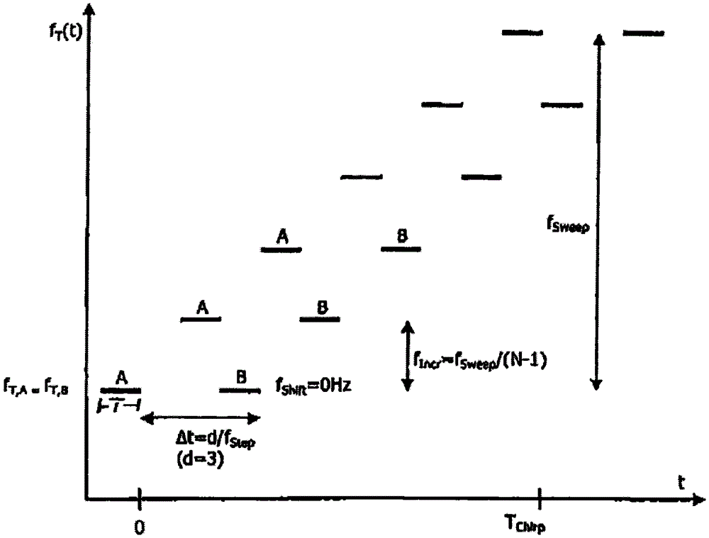
[0026] figure 1 A first signal A and a second signal B transmitted alternately are shown. The first signal A consists of a plurality of signal segments which are transmitted over a time period T. The duration T corresponds to about T=1 / f Step frequency f Step . Intervals of equal length are provided between the signal segments of signal A, during which intervals the signal segments of signal B can be transmitted. In the illustrated embodiment, the second signal B is delayed by a time dT(=d / f Step ), where d=3 here, so that no signal segment of the second signal is transmitted between the first two bursts of the first signal A. For interleaving without transmission pauses, d is an odd number and can therefore also be =5, for example.

[0027] exist figure 1 In the preferred embodiment shown in , the frequency steps between the signal segments of the first signal A and the signal segments of the second signal B are respectively constant f Incr , so that signals A and B a...


PUM


Abstract

The invention relates to a method for determining the distance (R) and relative speed (v) of at least one object remote from an observation point, comprising the following method steps: continuous transmission of at least one first and one second electromagnetic signal in each case of a signal period (Tchirp) from the observation point; the signals consist of signal portions (bursts) having a constant frequency and a predetermined equal duration, wherein the signal portions of a signal cover a predetermined modulation range by means of frequency steps; the signals are transmitted interlaced in that signal portions of the different signals follow one another in time, wherein a frequency hop occurs between the successive signal portions of different signals, receiving the signals reflected by the object as an echo signal and carrying out a mixed operation with the transmission signal for transformation of the received signal into the baseband in a common analog channel; carrying out an analog-to-digital conversion and sampling the received signal portions of the echo signals and extraction of at least one sampling value for each signal portion; separately evaluating the sampling values for the different echo signals of the different emitted signals by means of a Fourier transformation stage and determining the frequency of the peaks corresponding to signal portions and determining a phase difference between the echo signals of the transmitted signals, characterized in that the signal portions of the second signal (B) are transmitted by means of the same frequencies as corresponding signal portions of the first signal (A).

Description

technical field [0001] The invention relates to a method for determining the distance and the relative speed of at least one object remote from an observation point, said method comprising the following method steps: [0002] - continuous transmission of one signal period each from the observation point (T Chirp ) at least one first and second electromagnetic signal; [0003] - the signal consists of signal segments (bursts) with a constant frequency and a predefined same duration, wherein the signal segments of the signal are swept through a predefined modulation range by means of frequency steps; [0004] - sending said signals interleaved with each other by temporally connecting signal sections of different signals to each other, wherein there is a frequency jump between the mutually connected signal sections of different signals; [0005] - receiving the signal reflected by the object as an echo signal and performing a frequency mixing operation with the transmitted sign...

Claims


Application Information

Patent Timeline
IPC IPC(8): G01S13/58G01S13/34
CPCG01S13/343G01S13/347G01S13/584G01S7/356
Inventor R·蒙德F·基里施
Owner S M S SMART MICROWAVE SENSORS
Why Eureka
Try Eureka