Chain belts and chain belt pattern forming method

A pattern and chain belt technology, applied in clothing, printing, fasteners, etc., can solve the problems of difficult to see, invisible light-colored printed patterns, a lot of man-hours, cost, etc., and achieve the effect of suppressing light transmission

Inactive Publication Date: 2016-05-11
YKK CORP
View PDF9 Cites 6 Cited by
  • Summary
  • Abstract
  • Description
  • Claims
  • Application Information

AI Technical Summary

Problems solved by technology

However, in these methods, for example, when it is desired to change the shape, size, etc. of the printed pattern formed on the tape, there is a disadvantage that a lot of man-hours and costs are required.
[0021] In addition, in the case of transferring a pattern on a tape using a heat transfer sheet, or performing screen printing on

Method used


Image

  • Chain belts and chain belt pattern forming method
  • Chain belts and chain belt pattern forming method
  • Chain belts and chain belt pattern forming method

Examples


Embodiment 1

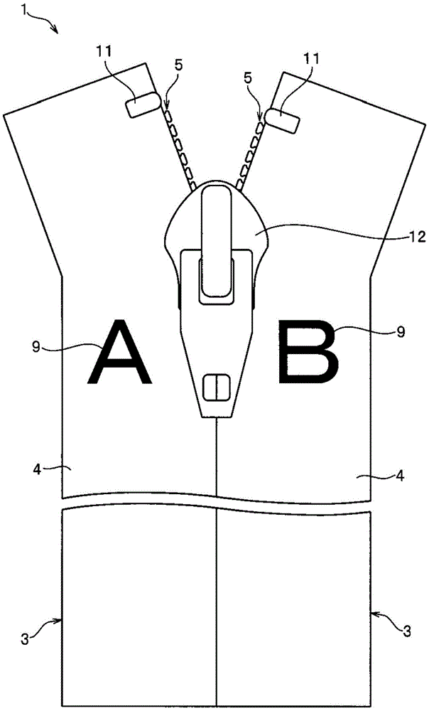
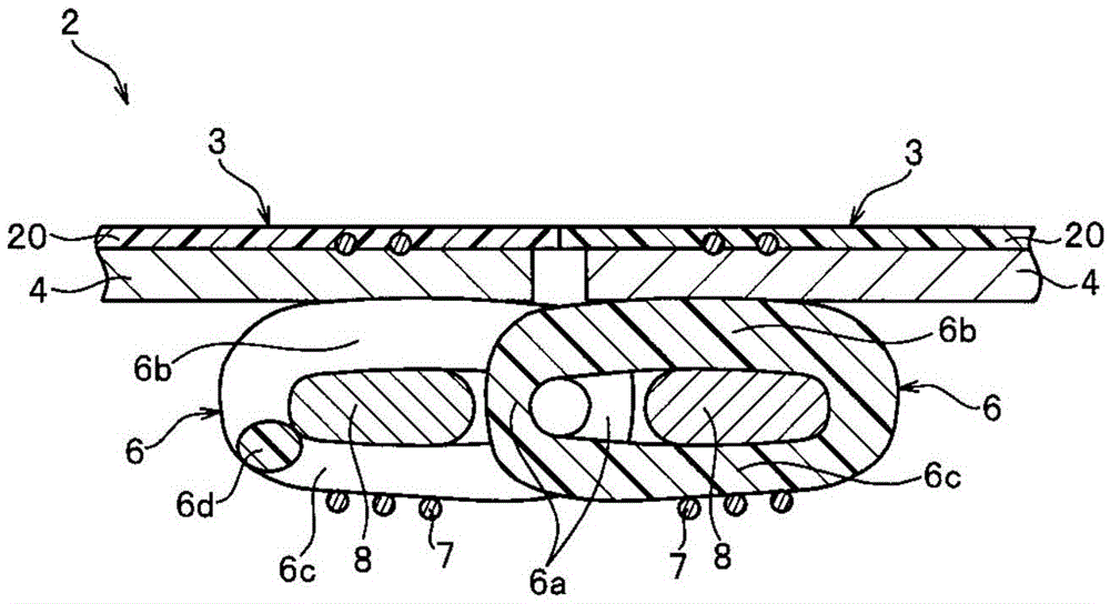
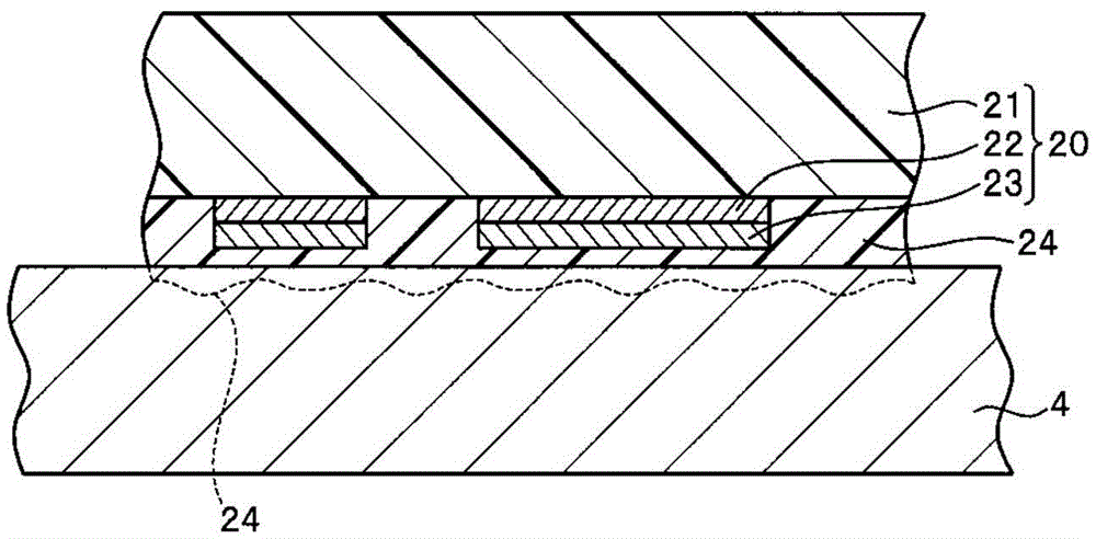
[0071] figure 1 It is a plan view showing the slide fastener of the present Example 1, figure 2 It is a sectional view of the fastener tape used for this slide fastener. image 3 It is an enlarged view of main parts showing enlargedly the bonded portion of the tape and the film member.

[0072] In addition, in the following description, the front-back direction means the tape length direction of a tape, and is the same direction as the sliding direction of a slider slide. In particular, the direction in which the slider is slid when the slide fastener is closed is defined as the front, and the direction in which the slider is slid when the slide fastener is opened is defined as the rear.

[0073] In addition, the left-right direction means the width|variety direction of a tape, and means the direction parallel to the tape surface of a tape and perpendicular|vertical to a tape length direction. In addition, the up-down direction refers to the front and back direction of the ...

Embodiment 2

[0126] Figure 6 It is a cross-sectional view showing the state before the film member is bonded to the tape in this Example 2.

[0127] In this second embodiment, when printing is performed on the film layer 21 to form the ink pattern portion 26 of the printed pattern, instead of using the pigment ink as in the above-mentioned embodiment 1, the dye ink that penetrates into the film layer 21 and is fixed is used. The film member 20a is formed. Therefore, in the film member 20a used in the present embodiment 2, the ink layer 22 like the aforementioned embodiment 1 is not formed between the film layer 21 and the cloth tape 4, but the structure other than that is the same as that of the aforementioned embodiment 1. Formed substantially in the same manner.

[0128] In addition, in the second embodiment, the third embodiment and the fourth embodiment described later, the description will focus on the configuration different from that of the first embodiment described above, and t...

Embodiment 3

[0135] Figure 7 It is a sectional view which shows the fastener tape of this Example 3.

[0136] The fastener tape 2 a of the present Example 3 has a pair of left and right fastener tapes 3 a, and each fastener tape 3 a has a tape 4 and an element row 5 formed along tape side edges of the tape 4 facing each other.

[0137] In this case, the fastener tape 2a of the third embodiment is formed in the form of a standard type (for the front) in which the element row 5 is attached to the tape front side of the cloth tape 4 and the element row 5 is exposed to the upper surface side of the slide fastener 1. .

[0138] Therefore, in the state where the core thread 8 penetrates between the upper leg part 6b and the lower leg part 6c of each fastener element 6, the fastener element 6 is sewn to the tape so that the lower leg part 6c contacts the tape 4. 4 on. In addition, the element line 5 itself of this Example 3 is formed similarly to the element line 5 of the said Example 1 menti...


PUM


Abstract

The invention provides chain belts and a chain belt pattern forming method. In a chain belt (2, 2a, 32) of the invention, a pattern visible surface of a cloth belt (4, 34a) is configured with a transparent thin film layer (21), a belt opposite surface of the thin film layer (21) is formed with an ink pattern portion (22, 26) formed by fixing ink. A belt opposite surface of the ink pattern portion (22, 26) is configured with a pigment layer (23) containing a pigment. A pattern non-forming region, having no ink pattern portion (22, 26), of the thin film layer and the pigment layer (23) are bonded to the cloth belt (4, 34a) through an adhesive layer (24). Thus, a printed pattern can be beautifully and stably attached to the pattern visible surface of the cloth belt (4, 34a) without being deformed, and the color of the ink pattern portion (22, 26) of the printed pattern can be less susceptible to the color of the cloth belt (4, 34a) and can be clearly displayed.

Description

technical field [0001] The present invention relates to a fastener chain having a printed pattern formed by printing and a pattern forming method for forming a printed pattern formed by printing on a fastener chain tape. Background technique [0002] In general, various designs are applied to clothing items, luggage items, and the like, and new designs are pursued for the purpose of increasing product value and the like. Zippers are often used for opening and closing portions of such clothing items, luggage items, and the like. In addition, design has been pursued for zippers used for these items recently, and zippers in which tapes and zipper elements are given various colors and patterns are already on the market. [0003] For example, as a method of applying patterns and colors to tapes, there is generally known a method of heat-treating the tape after pasting a heat-transfer sheet having a desired pattern or the like on the tape of the fastener tape for transfer. The m...

Claims


Application Information

Patent Timeline
IPC IPC(8): A44B19/24B41J3/407B41J2/01
CPCA44B19/34A44B19/24B41J2/01B41J3/407
Inventor 大西宽行朝垣文雄林亚己夫
Owner YKK CORP
Why Eureka
Try Eureka