
H-type fracture reduction joystick

A joystick and crossbar technology, applied in the field of medical equipment, can solve the problems of medical personnel injury, time-consuming and labor-intensive, insufficient precision, etc., and achieve the effects of easy portability and storage, reduced exposure time, and quick assembly.

Inactive Publication Date: 2018-07-10
SHENZHEN PEOPLES HOSPITAL
View PDF5 Cites 0 Cited by
  • Summary
  • Abstract
  • Description
  • Claims
  • Application Information

AI Technical Summary

Problems solved by technology

[0002] In clinical medicine, fractures of the femur, tibia, humerus and other extremity long tubular bones are common fractures. In the process of closed reduction and intramedullary nail internal fixation for fractures, the fracture can often be corrected after traction table traction and reduction of the stump. However, there are still angled, lateral, overlapping and rotational displacements of the broken ends. In clinical practice, the conventional method requires the assistance of doctors and assistants to perform the above-mentioned fracture reduction by hand, but this method is time-consuming. Laborious, and the precision is not enough, need more medical personnel to be exposed to X-ray, bring unnecessary injury to medical personnel, and bring unnecessary pain to patient, therefore, the reduction tool that is used for long tubular bone fracture is very difficult. important

Method used


Image

  • H-type fracture reduction joystick
  • H-type fracture reduction joystick

Examples


Embodiment 1

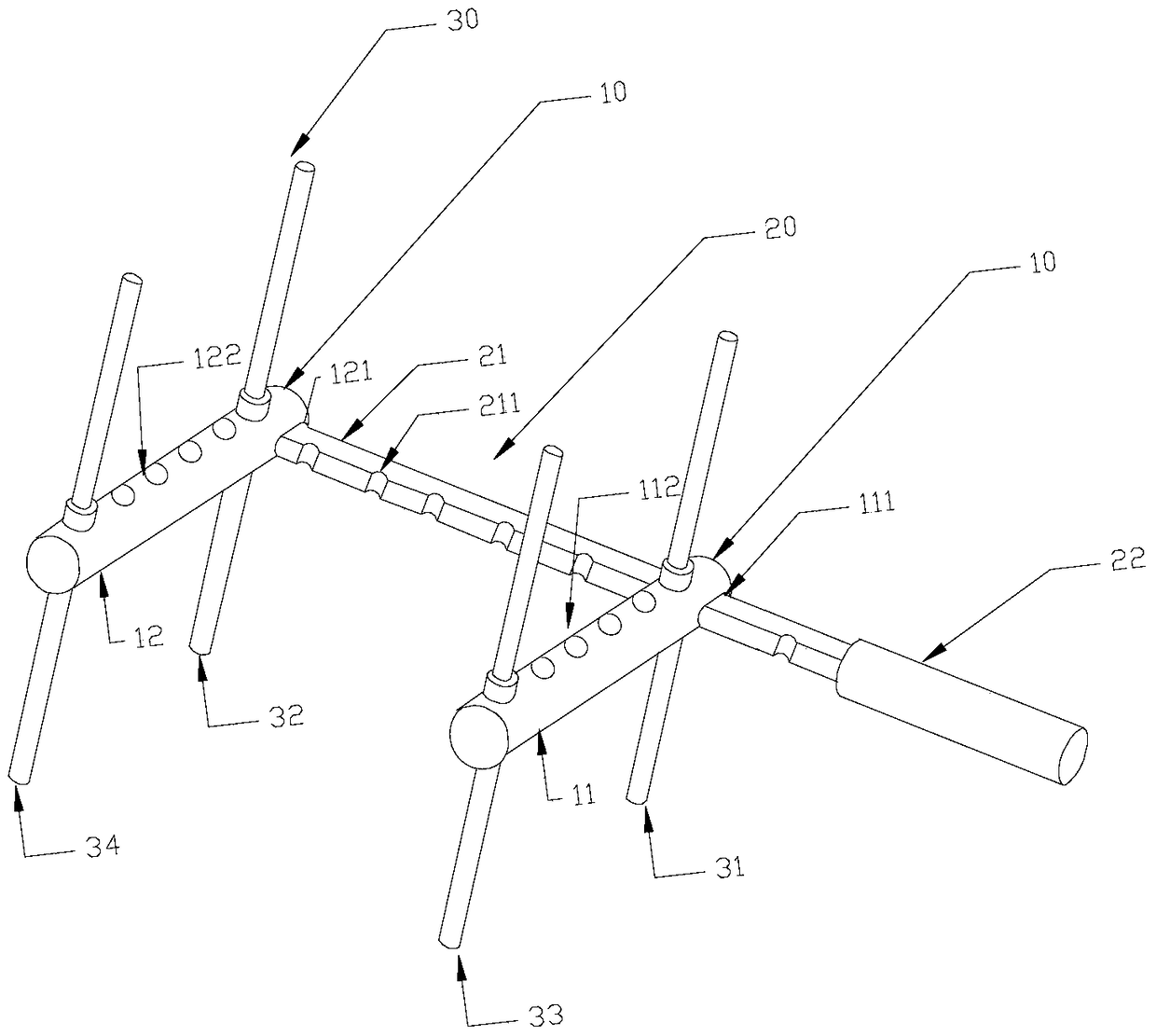
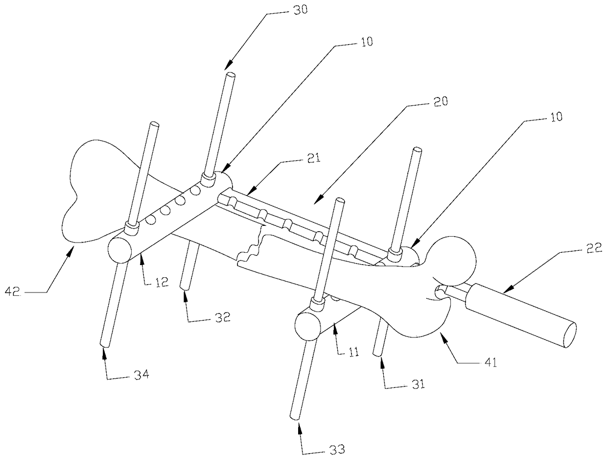
[0023] Embodiment one, such as figure 2 As shown, if the dislocation of the patient's fracture and bone is one-way up-down or one-way left-right dislocation, two cross bars 10, the main rod 20 and two auxiliary rods 30 can be used to realize the combination of the broken bone displacement. In this embodiment, the use of the joystick of the present invention is illustrated by taking the patient's fracture as an example where the broken bone 41 is lower and the broken bone 42 is higher. First, sterilize the required components at about 200°C. After cooling, insert the main operating rod 20 into the first through holes 111 and 121 on the same side of the two horizontal bars in turn. Select the main operating rod according to the length and thickness of the fracture site of the patient. Groove 211 at a suitable position on the 20, after the second through holes 112, 122 on the two crossbars are longitudinally aligned with the above-mentioned groove 211, insert the first subrod 31...

Embodiment 2

[0024] Embodiment 2, if the dislocation of the patient's fracture and bone is multi-directional dislocation at the same time up, down, left, and right, then it is necessary to use two crossbars 10, the main manipulation rod 20 and four auxiliary rods 30 to realize the displacement and combination of the broken bones. In this embodiment, the use of the H-type fracture reduction joystick of the present invention is illustrated by taking the multi-directional misalignment situation in which the broken bone 41 is lower to the left and the broken bone 42 is higher to the right as an example. On the basis of the components used in Embodiment 1, according to the thickness of the patient's fracture site, the third sub-rod 33 and the fourth sub-rod 34 are inserted into the idle suitable second bars of the first cross bar 11 and the second cross bar 12 respectively. In the through holes 112, 122, the H-type fracture reduction operating rod of the present invention can be formed, where th...


PUM


Abstract

An H-type fracture reduction control lever comprises two parallel cross rods 10 which are arranged in a spaced mode, a main operation lever body 20 capable of being perpendicular to the two cross rods 10 and detachably inserted in the ends, on the same side, of the two cross rods 10, and four auxiliary rods 30 detachably and perpendicularly inserted in the plane formed by the two cross rods 10 and the main operation lever body 20. The H-type fracture reduction control lever has the advantages of being capable of saving time and labor, reliable in precision, detachable, capable of achieving multi-direction reduction, high in adaptability and capable of relieving pains of patients.

Description

technical field [0001] The invention relates to the technical field of medical instruments, in particular to an H-type fracture reduction operating rod used in fracture reduction. Background technique [0002] In clinical medicine, fractures of the femur, tibia, humerus and other extremity long tubular bones are common fractures. In the process of closed reduction and intramedullary nail internal fixation for fractures, the fracture can often be corrected after traction table traction and reduction of the stump. However, there are still angled, lateral, overlapping and rotational displacements of the broken ends. In clinical practice, the conventional method requires the assistance of doctors and assistants to perform the above-mentioned fracture reduction by hand, but this method is time-consuming. Laborious, and the precision is not enough, need more medical personnel to be exposed to X-ray, bring unnecessary injury to medical personnel, and bring unnecessary pain to patie...

Claims


Application Information

Patent Timeline
Patent Type & Authority Patents(China)
IPC IPC(8): A61B17/88
CPCA61B17/8866A61B2017/0092
Inventor 胡新佳姜未周天健郑春丽林博文黎伟凡张晓明董文武
Owner SHENZHEN PEOPLES HOSPITAL
Learn More