Mold clamping device

A clamping device and mold technology, applied in fluid pressure actuating devices, forming tools, manufacturing tools, etc., can solve the problems of time-consuming, labor-consuming, cumbersome, etc.

Active Publication Date: 2016-05-11
CHONGQING TECH & BUSINESS UNIV
View PDF8 Cites 11 Cited by
  • Summary
  • Abstract
  • Description
  • Claims
  • Application Information

AI Technical Summary

Problems solved by technology

However, in production, the mold is mostly fixed on the equipment workbench by bolts. The replacement and adjustment of the mold requires frequent tightening and loosening of the mold fixing bolts, which is a very tedious, time-consuming and labor-intensive work.

Method used


Image

  • Mold clamping device
  • Mold clamping device
  • Mold clamping device

Examples


Embodiment Construction

[0016] The specific implementation process of the present invention will be described in further detail below in conjunction with the accompanying drawings.

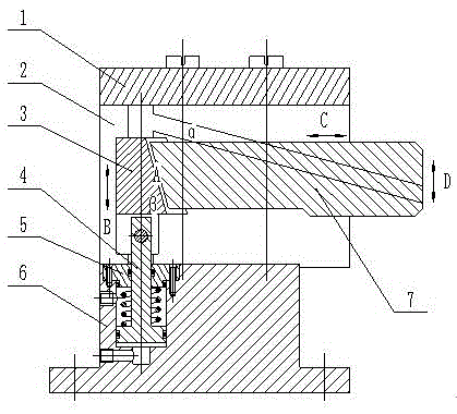
[0017] Such as figure 1 , The clamping device of the present invention consists of a base 6, a piston cover plate 5, a piston 4, a slider 3, a side plate 2, a pressure plate 1, and a clamping block 7. Wherein, the two side plates 2 are installed on the base 6, and the pressure plate 1 is installed on the side plates 2, and connected by bolts to form a frame-shaped unit.

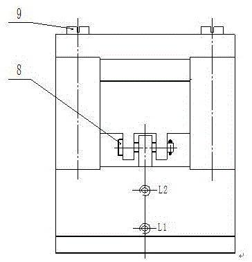
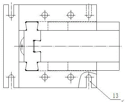
[0018] Such as figure 1 and image 3 As shown, the base 6 is designed with a piston hole, a threaded hole L1 of the oil inlet and a thread L2 of the breathing port, and a U-shaped groove connected with the equipment workbench is designed on the bottom surface thereof. Described piston 4 is installed in the piston hole on the base 6, and described base 6 doubles as the cylinder block of oil cylinder, and described piston 4, described piston cover plat...


PUM


Abstract

The invention discloses a mold clamping device. A sliding block and a clamping block of the mold clamping device are connected through an oblique surface with a dovetail section. The two side faces of the sliding block are each provided with a guiding boss, and the guiding bosses are matched with vertical guiding grooves in side plates. The two side faces of the clamping block are each provided with an oblique guiding boss, and the oblique guiding bosses are matched with oblique guiding grooves in the side plates. A piston installed on a base drives the sliding block to move up and down along the vertical guiding grooves in the two side plates installed on the base. Under the action of the oblique surface, the clamping block is pushed by the sliding block to move leftwards and rightwards and move upwards and downwards synchronously along the oblique guiding grooves in the side plates. A mold can be clamped and loosened through the up-down movement of the clamping block. According to the mold clamping device, the clamping force is converted by means of the oblique surface, and a good self-locking function is achieved; hydraulic driving is adopted, the clamping force is uniform and stable, and stepless adjustment of the clamping force can be achieved according to the size of the mold.

Description

technical field [0001] The invention relates to a mold clamping device, in particular to a clamping device capable of quickly loading and unloading a mold when the mold is replaced. Background technique [0002] Mold is an important process equipment in the production of modern products. Each product corresponds to one or a complete set of molds composed of multiple molds. As far as the same product is concerned, different molds will be used for different precision requirements. As the requirements for product performance are getting higher and higher, its structural shape and dimensional accuracy are also getting higher and higher. Similar products have various models and specifications, and the requirements for structural shape and precision are different; at the same time, in order to adapt to the rapid update of products In order to meet the needs of replacement or individualization, in the production of products, there will be more organizational forms for rapid mass p...

Claims


Application Information

Patent Timeline
IPC IPC(8): B21D37/04B29C33/30F15B11/08
CPCB21D37/04B29C33/30F15B11/08
Inventor 唐全波
Owner CHONGQING TECH & BUSINESS UNIV
Why Eureka
Try Eureka