
Motor-driven type automatic knife rest revolution device

An automatic knife, motor-driven technology, applied in feeding devices, metal processing machinery parts, metal processing equipment, etc., can solve the problems of low work efficiency and high labor intensity of personnel, and achieve high work efficiency, mechanized automation, and worker labor. low intensity effect

Inactive Publication Date: 2016-05-11
姜连生
View PDF0 Cites 0 Cited by
  • Summary
  • Abstract
  • Description
  • Claims
  • Application Information

AI Technical Summary

Problems solved by technology

[0003] The purpose of the present invention is to solve the above-mentioned technical problems such as low working efficiency and high labor intensity of personnel, and specially provides a motor-driven automatic tool holder turning device

Method used


Image

  • Motor-driven type automatic knife rest revolution device

Examples


Embodiment 1

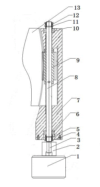
[0011] This embodiment provides a motor-driven automatic tool post rotary device, which is characterized in that: the motor-driven automatic tool post rotary device includes a driving machine (1), a reducer (2), an output shaft (3), The first nut (4), the first adjusting pad (5), the first bearing group (6), the sleeve (7), the lead screw (8), the worm (9), the second bearing group (10), the second Nut (11), second adjusting pad (12), knife rest (13);

[0012] Among them: the driving machine (1) is connected with the reducer (2), the reducer (2) is set on the output shaft (3) of the driving machine (1), the output shaft (3) is connected with the lead screw (8), the lead screw (8 ) The lower end is fixedly installed with the first bearing group (6) through the first nut (4), the first adjusting pad (5) is arranged between the first nut (4) and the first bearing group (6), and the lead screw (8 ) is installed with a worm (9) in the middle, and a shaft sleeve (7) is installed on...


PUM


Abstract

A motor-driven type automatic knife rest revolution device is characterized by comprising a driving machine, a decelerator, an output shaft, a first nut, a first adjusting cushion, a first bearing set, a bearing sleeve, a lead screw, a worm rod, a second bearing set, a second nut, a second adjusting cushion and a knife rest. The driving machine is connected with the decelerator; the decelerator covers the output shaft of the driving machine; the output shaft is connected with the lead screw; the lower end of the lead screw is fixedly connected with the first bearing set via the first nut; the first adjusting cushion is arranged between the first nut and the first bearing set; the worm rod is installed in the middle of the lead screw; a shaft sleeve covers the lead screw; the upmost end of the lead screw is fixedly connected with the second bearing set via the second nut; the second adjusting cushion is arranged between the second nut and the second bearing set; and the knife rest is arranged on one side of the worm rod. The motor-driven type automatic knife rest revolution device is advantageous in that the knife rest revolution device is driven by the motor; the revolution device has high work efficiency, requires low labor intensity; and mechanical and automatic work can be achieved.

Description

technical field [0001] The invention relates to the field of a rotary device for a vertical lathe, and in particular provides a motor-driven automatic tool post rotary device. Background technique [0002] Now, the rotary motion of the tool post on the beam slide can realize the machining of the conical surface on the workpiece, and the structural design of the rotary mechanism is conducive to improving work efficiency. Therefore, in the use of the rotary tool post, the rotary mode of the tool post determines the work Efficiency, among many factors affecting the turning force, the driving method of turning force is an extremely important one. Before the invention was made, the driving force of the rotating tool holder structure was to rotate with a square socket wrench to achieve the purpose of turning at a certain angle. , but in this structure, due to the use of manpower, the labor intensity of the workers is high, and the work efficiency is low. Obviously, the traditional...

Claims


Application Information

Patent Timeline
Patent Type & Authority Applications(China)
IPC IPC(8): B23Q5/40B23B21/00
Inventor 姜连生
Owner 姜连生
Learn More