Robot vision guide method used for shaft hole assembling

A robot vision and robotics technology, applied in manipulators, program-controlled manipulators, manufacturing tools, etc., can solve problems such as difficult to meet high-precision requirements, primary methods and means, and achieve the effect of improving the degree of automation and accuracy

Active Publication Date: 2016-05-11
SHENYANG SIASUN ROBOT & AUTOMATION
View PDF4 Cites 16 Cited by
  • Summary
  • Abstract
  • Description
  • Claims
  • Application Information

AI Technical Summary

Problems solved by technology

At present, machine vision is rarely used in the field of intelligent assembly, and the methods are still relatively elementary. For

Method used


Image

  • Robot vision guide method used for shaft hole assembling
  • Robot vision guide method used for shaft hole assembling
  • Robot vision guide method used for shaft hole assembling

Examples


Embodiment Construction

[0030] In order to make the purpose, technical solutions and advantages of the embodiments of the present invention more clear, the technical solutions in the embodiments of the present invention will be clearly and completely described below in conjunction with the embodiments of the present invention and the accompanying drawings. It should be noted that the described embodiments are only some of the embodiments of the present invention, but not all of the embodiments. Based on the embodiments of the present invention, all other embodiments obtained by persons of ordinary skill in the art without making creative efforts belong to the protection scope of the present invention.

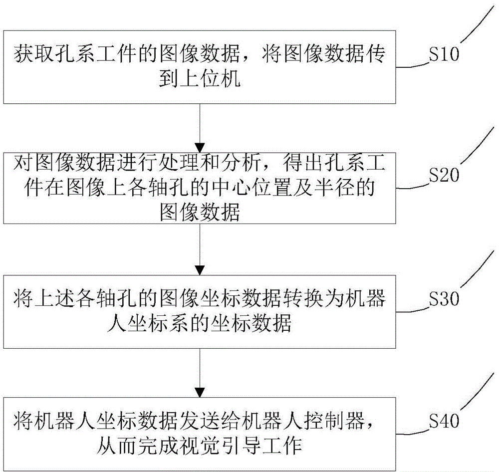
[0031] Such as figure 1 As shown, a robot vision-guided method for shaft-hole assembly includes the following steps:

[0032] S10: Use an industrial camera to take pictures of the hole system workpiece, obtain the image data of the hole system workpiece, and transmit the image data to the host comput...


PUM


Abstract

The invention provides a robot vision guide method used for shaft hole assembling. An industrial camera is used for taking an image of a hole system workpiece, obtaining the image data of the hole system workpiece and transmitting the image data to an upper computer. The upper computer carries out image processing and analysis on the image data, and the image data of the center position and the radius of each shaft hole of the hole system workpiece on the image are obtained. The image coordinate data of each shaft hole are converted into coordinate data of a robot coordinate system. The robot coordinate data are sent to a robot controller, and therefore vision guide work is completed. The robot vision guide method used for shaft hole assembling improves the accuracy and stability of intelligent assembling with an industrial robot, and improves the automation degree.

Description

technical field [0001] The invention relates to the field of robot control, in particular to a robot vision guidance method for shaft hole assembly. Background technique [0002] In modern manufacturing, industrial robots are widely used in various production needs, such as welding, spraying, palletizing, assembly, etc. It can not only liberate workers from complicated labor tasks, but also improve the quality of products and the automation level of production lines, greatly improving work efficiency. Especially, in the part assembly production task, the multi-axis hole assembly task is one of the common task types. In this case, multiple pairs of shaft holes have assembly relationships at the same time, and industrial robots are required to automatically and accurately position while satisfying the correct assembly correspondence. More importantly, there is a need to avoid collisions between the two workpieces which could lead to defects. Therefore, it can be seen that t...

Claims


Application Information

Patent Timeline
IPC IPC(8): B25J9/16B25J19/02
Inventor 宋吉来曲道奎刘晓帆钱益舟韩志平孙秉斌
Owner SHENYANG SIASUN ROBOT & AUTOMATION
Why Eureka
Try Eureka