O-shaped ring forming mold
A technology for forming molds and O-rings, applied in the field of molds, can solve the problems of difficulty in taking out templates layer by layer, high labor costs, and long blanking time, so as to save time and economic costs, reduce labor intensity, and improve production efficiency Effect
- Summary
- Abstract
- Description
- Claims
- Application Information
AI Technical Summary
Problems solved by technology
Method used
Image
Examples
Embodiment 1
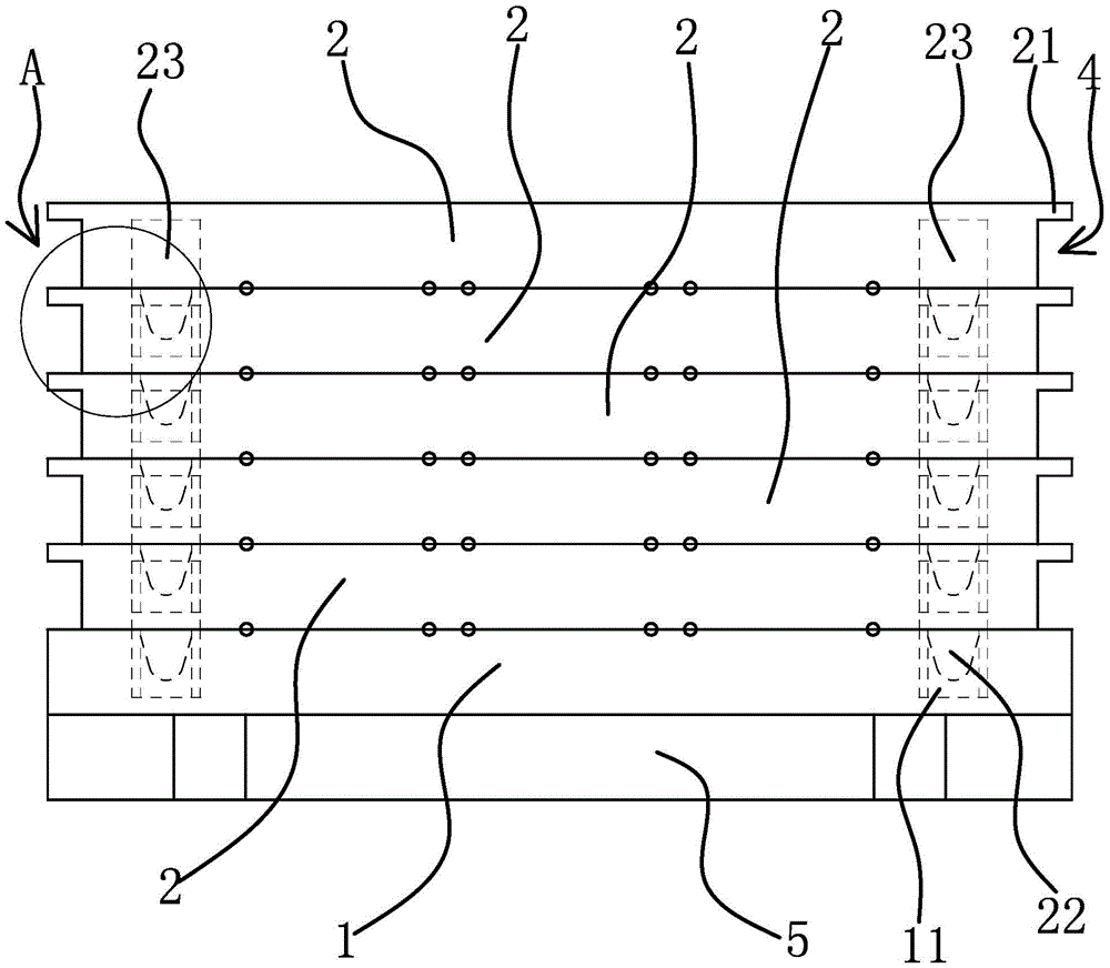
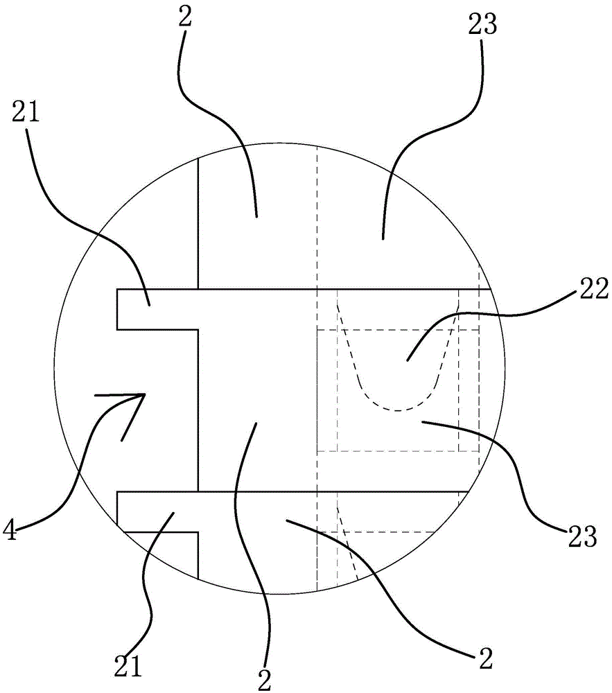
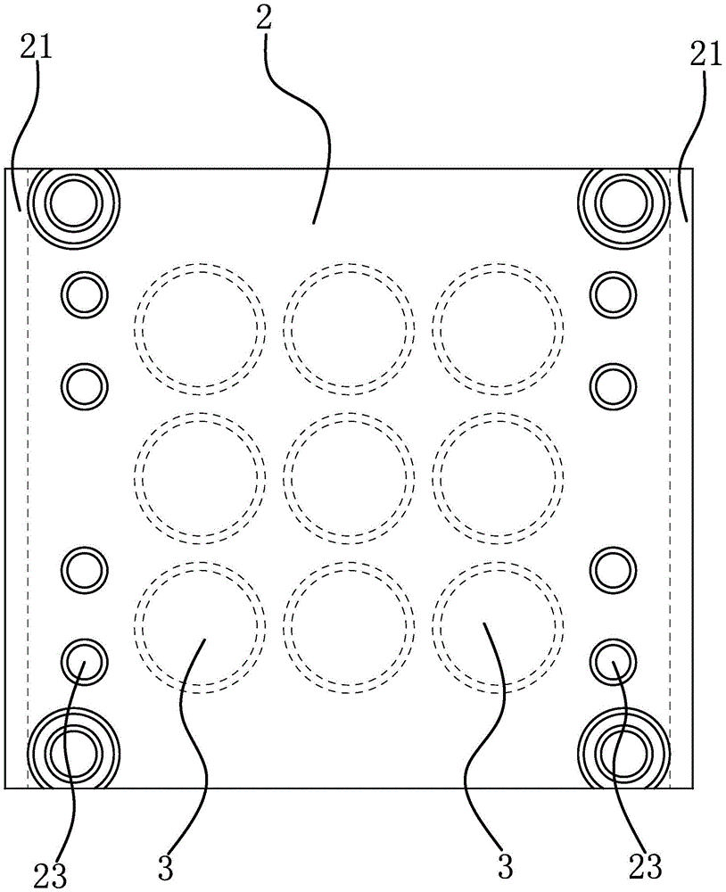
[0024] The O-ring forming mold includes a fixed template 1 , a movable template 2 , a cavity 3 , a clamping part 21 and a clamping notch 4 .
[0025] Specifically, as figure 1 and 3 As shown, the fixed template 1 is installed on the mounting plate 5 . In this embodiment, the number of movable templates 2 is five, and the movable templates 2 are superimposed on the fixed template 1. The fixed template 1, the movable template 2 adjacent to the fixed template 1, and the upper and lower surfaces of the two adjacent movable templates 2 The mold cavities 3 can be bonded to each other, so that the number of practical mold cavities 3 in one molding process can be greatly increased. In the actual production and manufacturing process, the number of movable templates 2 is at least two.
[0026] Such as figure 1 and figure 2 As shown, each movable template 2 has a strip-shaped clamping portion 21 protruding from the side of the movable template 2 on both sides, the clamping portion ...
Embodiment 2
[0030]The technical solution in this embodiment is basically the same as the technical solution in Embodiment 1. The difference is that in this embodiment, the positioning structure includes a positioning step 1 located on the upper surface of the movable template 2 and a positioning step 1 located on the lower surface of the movable template 2. The gap, the positioning step one is flush with the outer surface of the movable template 2, the positioning gap extends to the side of the movable template 2 and is directly opposite to the positioning step one, and the positioning step one on the movable template 2 can be snapped into the positioning position on the adjacent movable template 2 inside the gap. The positioning structure also includes a positioning step 2 located on the upper surface of the fixed template 1, the positioning step 2 is flush with the outer surface of the fixed template 1, and the positioning step 2 on the fixed template 1 can be snapped into the positionin...
PUM
| Property | Measurement | Unit |
|---|---|---|
| thickness | aaaaa | aaaaa |
| thickness | aaaaa | aaaaa |
Abstract
Description
Claims
Application Information
 - R&D
- Intellectual Property
- Life Sciences
- Materials
- Tech Scout
- Unparalleled Data Quality
- Higher Quality Content
- 60% Fewer Hallucinations
Browse by: Latest US Patents, China's latest patents, Technical Efficacy Thesaurus, Application Domain, Technology Topic, Popular Technical Reports.
© 2025 PatSnap. All rights reserved.Legal|Privacy policy|Modern Slavery Act Transparency Statement|Sitemap|About US| Contact US: help@patsnap.com


