Downhole electronic triggering and actuation mechanism

a technology of electronic triggering and actuation mechanism, which is applied in the direction of survey, borehole/well accessories, construction, etc., can solve the problems of complex, hydraulically actuated anchor, and complicated valve system function, and achieves the effect of improving reliability, reducing the cost of operation and maintenance, and improving the reliability of the valve system

Active Publication Date: 2019-11-28
WILDCAT OIL TOOLS LLC
View PDF0 Cites 1 Cited by
  • Summary
  • Abstract
  • Description
  • Claims
  • Application Information

AI Technical Summary

Benefits of technology

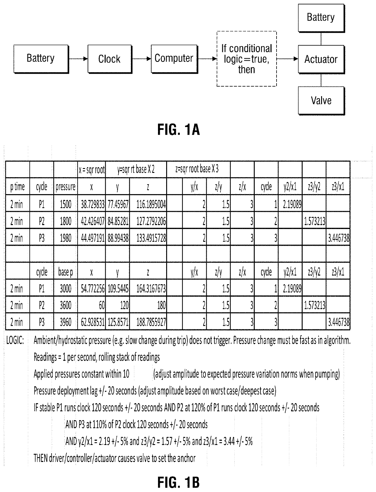
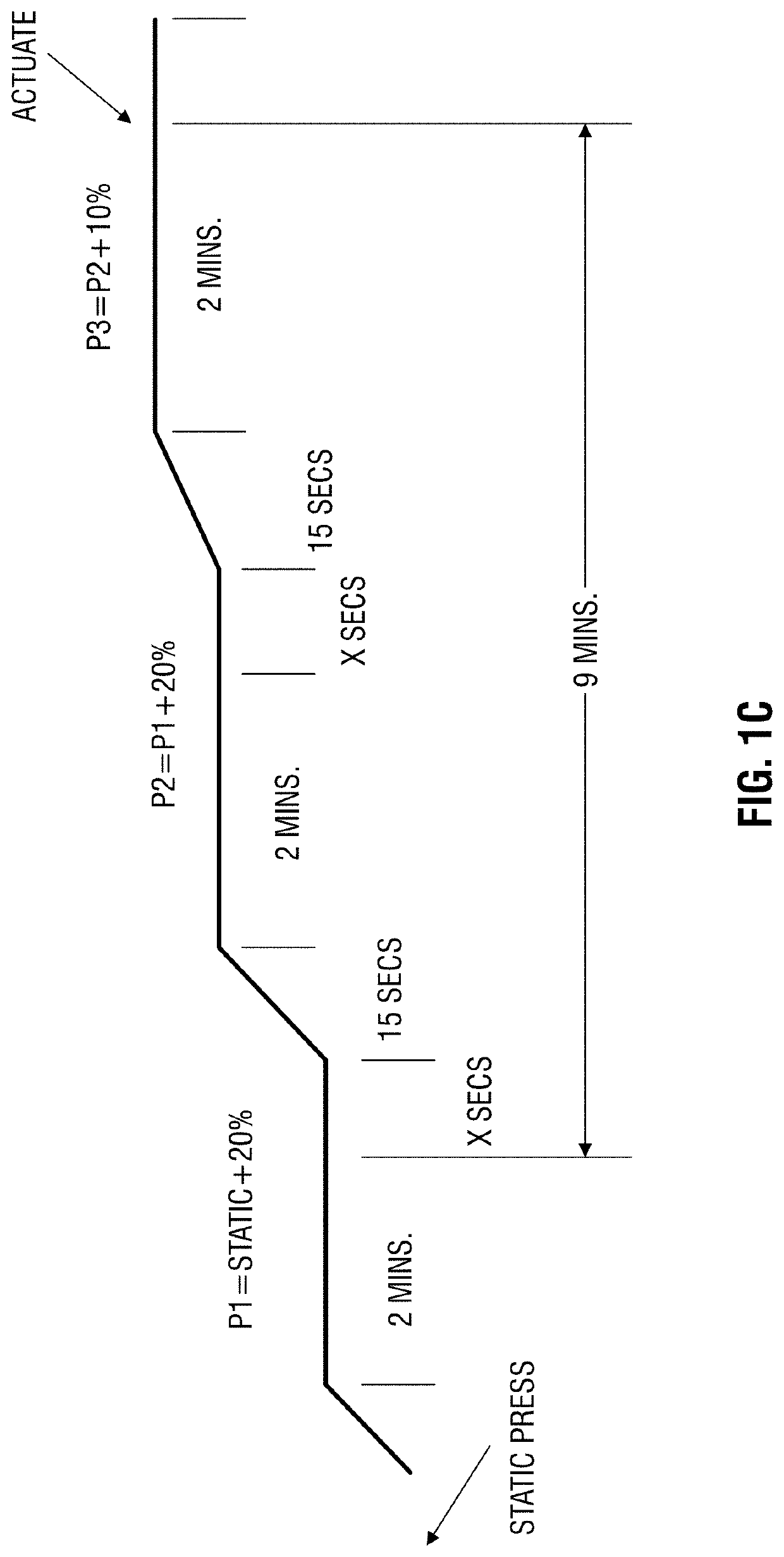
[0008]The present disclosure details a method, system, and fabrication method for a different, more reliable, more precise triggering and actuation mechanism that can consistently close off circulation to the annulus and set the anchoring device at the appropriate time and at the appropriate depth, generally after a device, e.g. MWD, has oriented the whipstock to the proper azimuth / direction. The disclosed apparatus does not use specific pressures to trigger a setting device, but rather uses ratios of pressure increases. The disclosed apparatus solves premature setting issues through electronic means, only triggering a setting mechanism after observed pressure ratios are analyzed and confirmed to match preprogrammed parameters. The disclosed apparatus solves issues that could result from unexpected pressure spikes in the wellbore pressure or from inadequate pump capacity to generate target pressures, as no specific target pressure is necessary and aberrant pressure events have no effect on the electronically executed process.

Problems solved by technology

In many cases, however, a more complex, hydraulically actuated anchor, is required.
A general weakness of hydraulic anchor systems lies in the hydromechanical valve system(s) that actuate these anchors.
Wellbore debris, erosion, and “Measurement While Drilling” (MWD) / directional systems can complicate the function of such valve systems.
Reliability issues are common.
In the prior art, problems persist with setting an anchor too soon, i.e. at a higher depth in the wellbore than the target depth.

Method used


Image

  • Downhole electronic triggering and actuation mechanism
  • Downhole electronic triggering and actuation mechanism
  • Downhole electronic triggering and actuation mechanism

Examples


Embodiment Construction

[0039]Various embodiments of the expandable anchor and methods of use will now be described with reference to the accompanying drawings, wherein like reference numerals are used for like features throughout the several views. The detailed description set forth below in connection with the appended drawings is intended as a description of exemplary embodiments in which the presently disclosed subject matter can be practiced. The term “exemplary” used throughout this description means “serving as an example, instance, or illustration,” and should not necessarily be construed as preferred or advantageous over other embodiments. The detailed description includes specific details for providing a thorough understanding of the presently disclosed method and system. However, it will be apparent to those skilled in the art that the presently disclosed subject matter may be practiced without these specific details. In some instances, well-known structures and devices are shown in functional o...


PUM


Abstract

A triggering mechanism for downhole equipment includes a housing for inserting downhole in an oilfield wellbore and associating downhole with a computer processor, a clock, at least one sensor circuit, and an electrical power source. The computer processor includes computer processing circuitry and a computer readable memory circuit. The sensor circuit senses at least a pressure parameter associated with the pressure within the oilfield wellbore downhole environment. A valve control circuit controls a valve and controls flow of control fluid to a hydromechanical device operating in association with the downhole tool within the oilfield wellbore. The valve control commands derive from real-time sampling of the downhole physical parameters to form ratio-based derivative values relating to physical parameter differences over a predetermined time span. In response to the ratio-based derivative values, the triggering mechanism generates triggering commands for flowing the control fluid to the associated hydromechanical device.

Description

CROSS REFERENCE TO RELATED APPLICATIONS[0001]This application claims the benefit of the following patent applications:[0002]U.S. Provisional Patent Application 62 / 696,423 entitled “Dual-Action Hydraulically Operable Anchor,” filed on Jul. 11, 2018 with Attorney Docket No. WILD002USP, which is here expressly incorporated by reference;[0003]U.S. Provisional Patent Application 62 / 696,750 entitled “Dual-Action Hydraulically Operable Anchor,” filed on Jul. 11, 2018, also with Attorney Docket No. WILD002USP, which is here expressly incorporated by reference;FIELD OF THE DISCLOSURE[0004]The present disclosure relates generally to oilfield drilling and completion equipment and more particularly to downhole electronic triggering apparatus for use in harsh environments, such as downhole in a wellbore in the oil and gas industry, in conjunction with other electro-mechanical components requiring conditional actuation.BACKGROUND OF THE DISCLOSURE[0005]In the oil and gas industry, wellbores devia...

Claims


Application Information

Patent Timeline
Patent Type & Authority Applications(United States)
IPC IPC(8): E21B34/10E21B47/06E21B23/04
CPCE21B34/066E21B21/08E21B47/017E21B34/10E21B47/06E21B34/085
Inventor ALLEY, MARK F.
Owner WILDCAT OIL TOOLS LLC
Why Eureka
Try Eureka