Automatic stamping device

An automatic, sliding connection technology, applied in the direction of printing, stamping, etc., to achieve the effect of appropriate ink depth

Inactive Publication Date: 2020-11-17
哈尔滨冕轩会计服务有限公司
View PDF1 Cites 1 Cited by
  • Summary
  • Abstract
  • Description
  • Claims
  • Application Information

AI Technical Summary

Problems solved by technology

However, this patent cannot have a suitable strength when stamping, so that the ink depth is suitable

Method used


Image

  • Automatic stamping device
  • Automatic stamping device
  • Automatic stamping device

Examples


specific Embodiment approach 1

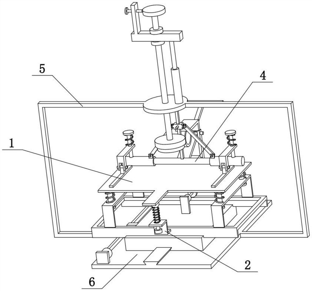
[0028] Combine below Figure 1-8 Describe this embodiment mode, the present invention relates to a kind of accounting appliance, more specifically a kind of automatic stamping device, including flat plate 1, door-shaped plate 102, rectangular frame 103, round baffle 1104 and vertical column 105, the present invention can There is a suitable strength when stamping, so that the ink depth is suitable.

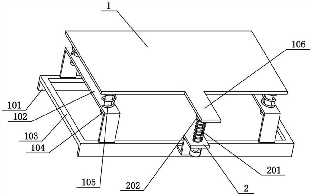
[0029] The left and right ends of the upper side of the rectangular frame 103 are fixedly connected with door-shaped plates 102, and the four corners of the lower side of the flat plate 1 are fixedly connected with vertical columns 105, and the two vertical columns 105 at the left end are slidably connected with each other at the left end. On the door-shaped plate 102, the two vertical columns 105 at the right end are slidably connected to the door-shaped plate 102 at the right end, and the four vertical columns 105 are sleeved with compression springs I, and the four compression ...

specific Embodiment approach 2

[0031] Combine below Figure 1-8 To illustrate this embodiment, the automatic stamping device also includes a front convex plate 106, a folding plate 2, a hammer post 201 and a ball 202, the front side of the flat plate 1 is fixedly connected with the front convex plate 106, and the front side of the rectangular frame 103 is fixed. The folding plate 2 is connected, the hammer column 201 is vertically slidingly connected to the folding plate 2, the upper end of the hammer column 201 is fixedly connected with a ball 202, the ball 202 is located under the front convex plate 106, and the hammer column 201 is sleeved with a compression Spring II, the compression spring II is located between the front flange 106 and the flap 2 . The compression spring II can be stored by pulling the hammer column 201, and then when the hammer column 201 is released, the ball 202 is pushed forward by the action of the compression spring II to the forward convex plate 106, so that the plate 1 vibrates...

specific Embodiment approach 3

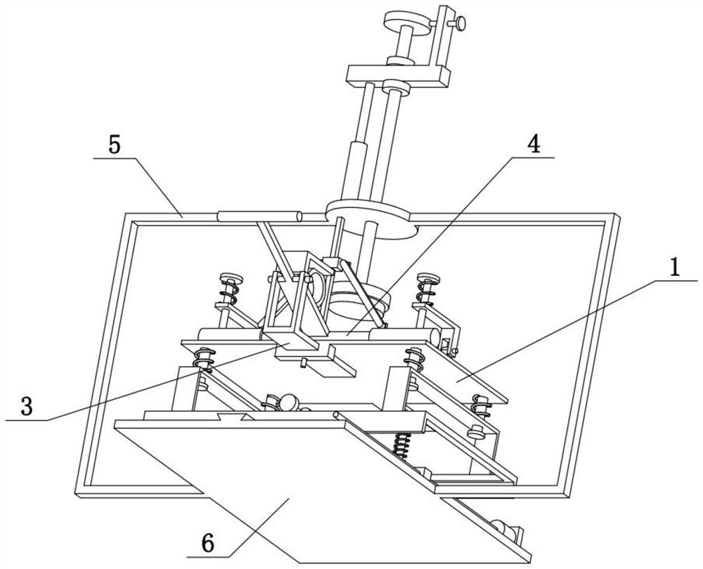
[0033] Combine below Figure 1-8 To illustrate this embodiment, the automatic stamping device also includes a fixed seat 107, a front and rear moving plate 3, a lever 301, a hinged frame 302, an L-shaped seat 303 and a rubber ring 304, and the lower rear portion of the flat panel 1 is fixedly connected with a fixed seat 107, the front and rear moving plates 3 are slidably connected to the fixed seat 107 in the front and rear direction, and the front and rear moving plates 3 and the fixed seats 107 are fixed by means of screw compression, and the rear of the front and rear moving plates 3 is fixedly connected with a hinged frame 302, The middle part of the lever 301 is hinged on the upper part of the hinged frame 302, the upper end of the hinged frame 302 is fixedly connected with an L-shaped seat 303, the lower side of the L-shaped seat 303 is fixedly connected with a rubber ring 304, and the rubber ring 304 is pressed on the upper side of the front end of the lever 301 . The r...


PUM


Abstract

The invention relates to an accounting tool, in particular to an automatic stamping device which comprises a flat plate, door-shaped plates, a rectangular frame, round blocking pieces I and vertical cylinders. Proper force can be realized during stamping, so that the depth of printing ink is proper. The door-shaped plates are fixedly connected to the left end and the right end of the upper side ofthe rectangular frame correspondingly, the vertical cylinders are fixedly connected to the four corners of the lower side of the flat plate correspondingly, the two vertical cylinders located at theleft end are slidably connected to the door-shaped plate located at the left end, and the two vertical cylinders located at the right end are slidably connected to the door-shaped plate located at theright end. The four vertical cylinders are sleeved with compression springs I, the four compression springs I are located on the upper sides of the two door-shaped plates, the lower ends of the fourvertical cylinders are fixedly connected with the round blocking pieces I, and the four round blocking pieces I are located on the lower sides of the two door-shaped plates. The automatic stamping device further comprises a front protruding plate, a folding plate, a hammer column and a ball, the front protruding plate is fixedly connected to the front side of the flat plate, and the folding plateis fixedly connected to the front side of the rectangular frame.

Description

technical field [0001] The invention relates to an accounting appliance, more specifically an automatic stamping device. Background technique [0002] The application number is CN201820525391.2, which discloses a convenient accounting stamping device. The utility model provides a convenient accounting stamping device, which relates to the technical field of office supplies. The accountant's convenient stamping device comprises a stamping device bottom plate, fixed rods are fixedly connected to both sides of the upper surface of the stamping device bottom plate, a stamping device top plate is arranged above the stamping device bottom plate, and the fixed One end of the rod away from the bottom plate of the stamping device is fixedly connected to the top plate of the stamping device, a slide block is arranged below the top plate of the stamping device, and an electric push rod is fixedly connected to the lower surface of the slide block, and the top plate of the stamping devic...

Claims


Application Information

Patent Timeline
Patent Type & Authority Applications(China)
IPC IPC(8): B41K3/04B41K3/62
CPCB41K3/04B41K3/62
Inventor 闫玉娥
Owner 哈尔滨冕轩会计服务有限公司
Why Eureka
Try Eureka