Washing machine deceleration clutch and washing machine

A deceleration clutch and washing machine technology, applied in the field of washing machines, can solve the problems of motor leakage, excessive, water overflowing from the tub, falling to the ground between the washing machine shell and the outer tub, failures, etc., so as to achieve easy installation and disassembly. Effect

Active Publication Date: 2016-05-11
QINGDAO HAIER WASHING MASCH CO LTD
View PDF8 Cites 2 Cited by
  • Summary
  • Abstract
  • Description
  • Claims
  • Application Information

AI Technical Summary

Problems solved by technology

Therefore, if the washing machine has a water leakage failure, the washing water may enter directly from the upper part of the motor, causing electric leakage or failure of the motor; or if other control components of the washing machine fail to cause excessive water intake, the water overflows from the bucket and falls into the washing machine shell and the ground between the outer barrel, and then splashed on the winding of the motor, causing the motor to leak or malfunction

Method used


Image

  • Washing machine deceleration clutch and washing machine
  • Washing machine deceleration clutch and washing machine
  • Washing machine deceleration clutch and washing machine

Examples


Embodiment 1

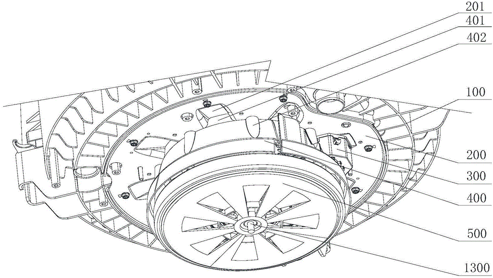
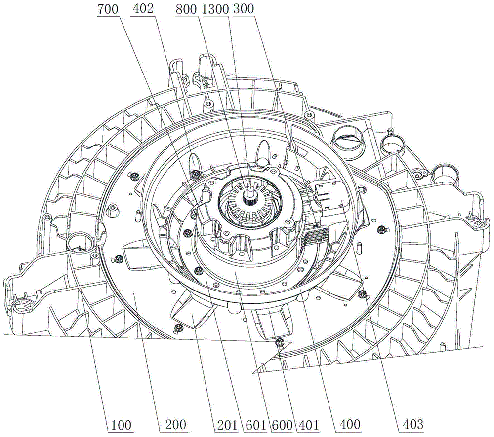
[0066] Such as figure 1 , figure 2 and image 3 As shown, a washing machine deceleration clutch described in this embodiment includes a deceleration clutch device, a mounting plate 200 and a motor 500. The deceleration clutch device is fixed on the bottom of the washing machine outer tub 100 through the mounting plate 200, and the motor 500 is arranged on The lower part of the deceleration clutch device. The deceleration clutch device includes a deceleration device and a clutch device; the deceleration device includes a gear train and a housing, the housing is fixedly mounted on the mounting plate 200, and the gear train is arranged inside the housing; the described clutch device includes an upper fixed plate, The clutch sleeve and the lower dehydration tray 800 that can slide up and down, and the clutch sleeve slides up and down to engage with the upper fixed tray and the lower dehydration tray 800 respectively to realize the conversion of washing and dehydration working c...

Embodiment 2

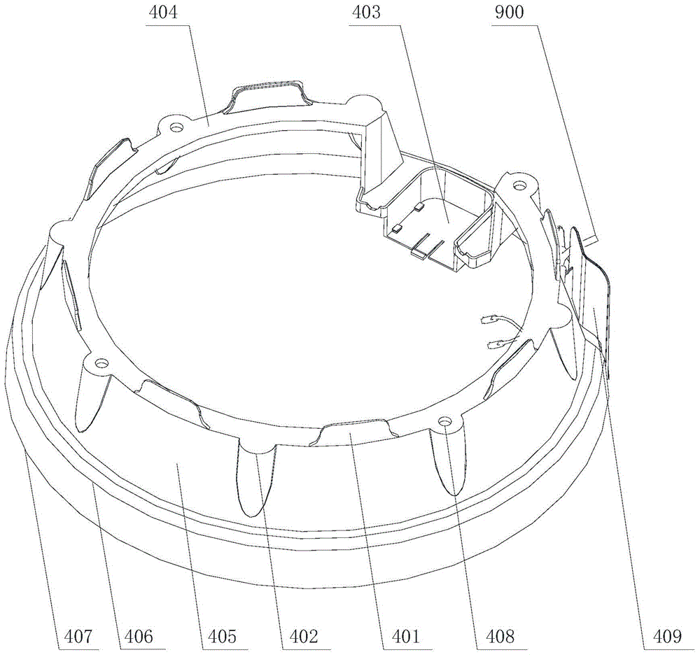
[0087] Such as Figure 1-Figure 3 , Figure 7-Figure 9 A washing machine deceleration clutch shown includes a deceleration clutch device, a mounting plate 200 and a motor 500. The deceleration clutch device is fixed on the bottom of the outer tub 100 of the washing machine through the mounting plate 200, and the motor 500 is arranged at the bottom of the deceleration clutch device. The deceleration clutch device of the washing machine of the present invention also includes a protective cover, the protective cover includes a cover body 400, and the cover body 400 is fixedly installed on the mounting plate 200; part or all of the deceleration clutch device and / or part or all of the motor 500 Set inside the cover body 400 . The cover body of the protective cover 400 of the present embodiment is installed on the mounting plate 200, does not produce influence to the installation of deceleration clutch device and motor 500, and deceleration clutch device and motor 500 are all arran...


PUM


Abstract

The invention provides a washing machine deceleration clutch comprising a deceleration clutch device, an installation plate and a motor. The deceleration clutch device is fixed on the bottom of an outer barrel of the washing machine via the installation plate; the motor is arranged on the lower part of the deceleration clutch device; the washing machine deceleration clutch comprises a protection cover; the protection cover has a cover body; the cover body is fixed on the installation plate; the deceleration device is partially or fully and / or the motor is partially or fully disposed in the cover body; the deceleration clutch device has a clutch driving device driving motion of a clutch shaft sleeve; the clutch driving device is partially or fully disposed in the cover body; and the cover body is provided with an installation part for fixed installation of the clutch driving device. The deceleration clutch device and the motor can be protected and the installation part on the cover body prevents effects on installation of the driving device of the deceleration device.

Description

technical field [0001] The invention relates to the technical field of washing machines, in particular to a washing machine deceleration clutch and a washing machine. Background technique [0002] As a daily household appliance, washing machine liberates people from the labor of doing laundry, so it is very popular among users. Existing washing machines are usually powered by a motor, and the motor transmits power to the pulsator of the washing machine through a deceleration clutch to drive the pulsator to rotate to achieve washing and dehydration. Therefore, the motor is an indispensable important part of the washing machine. [0003] Existing washing machines usually use direct-drive motors as the power output. For example, the application number is 201210414891.6, which is called a washing machine reducer and motor installation structure and a Chinese invention patent for washing machines. The invention discloses a washing machine reducer and motor installation. Structur...

Claims


Application Information

Patent Timeline
Patent Type & Authority Applications(China)
IPC IPC(8): D06F37/40
Inventor 田云张刚金张琪李峰
Owner QINGDAO HAIER WASHING MASCH CO LTD
Why Eureka
Try Eureka