Flexible blocking net with additional connecting structure
A technology for connecting structures and retaining nets, which is applied in infrastructure engineering, protective equipment, excavation, etc., to achieve the effects of optimizing load distribution, reducing replacement or maintenance requirements, and improving cost performance
- Summary
- Abstract
- Description
- Claims
- Application Information
AI Technical Summary
Problems solved by technology
Method used
Image
Examples
Embodiment 1
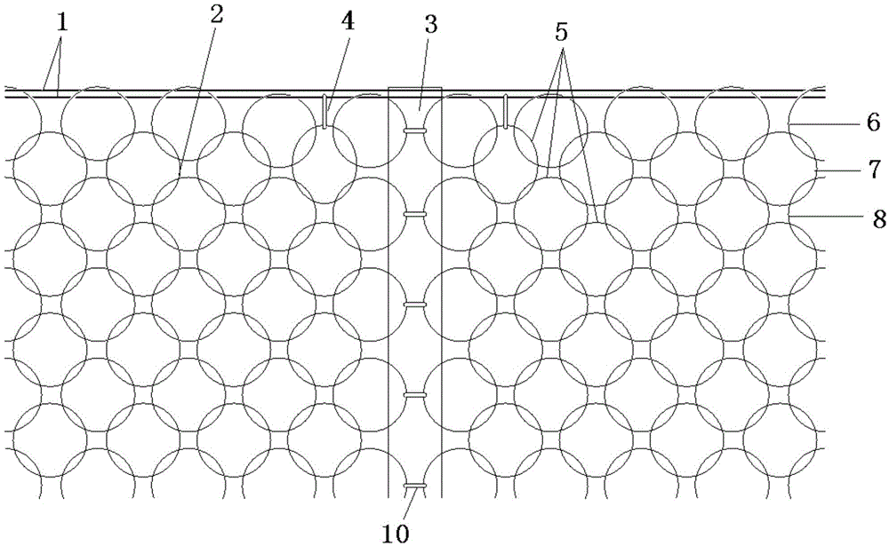
[0030] Such as figure 1 As shown, the top of the end support column and the middle support column 3 are horizontally deployed with two sets of top support ropes 1 , and two adjacent flexible metal meshes 2 are connected by connecting pieces 10 near the middle support column 3 . At the support node where the top support rope 1 intersects with the middle support column 3, the two mesh holes next to the middle support column 3 in the second row of mesh holes 7 of the metal flexible net 2 are added through the connecting ring 4 and a set of top support rope 1. At the same time, the four edge meshes 6 nested with the two secondary row meshes 7 are also connected to the group of top support ropes 1, and other edge meshes 6 of the metal flexible mesh 2 are connected with another Set the top support rope to 1 connection.
Embodiment 2
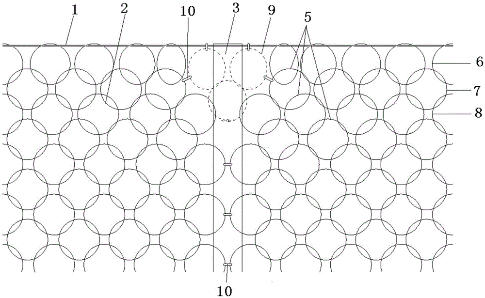
[0032] Such as figure 2 As shown, there is only one group of top support ropes 1 horizontally deployed on the top of the end support column and the middle support column 3, and the edge meshes 6 of the metal flexible net 2 are all connected with the top support rope 1. Three additional meshes 9 are added at the support node where the top support rope 1 intersects with the middle support column 3, wherein two additional meshes 9 are respectively connected to the top support rope 1 and the second row of mesh holes 7 through the connector 10. Two connections adjacent to the middle support column 3. Another additional mesh 9 is socketed with the above two additional meshes 9, and is socketed with two of the three rows of meshes 8 of the metal flexible mesh 2 that are closest to the middle support column 3.
Embodiment 3
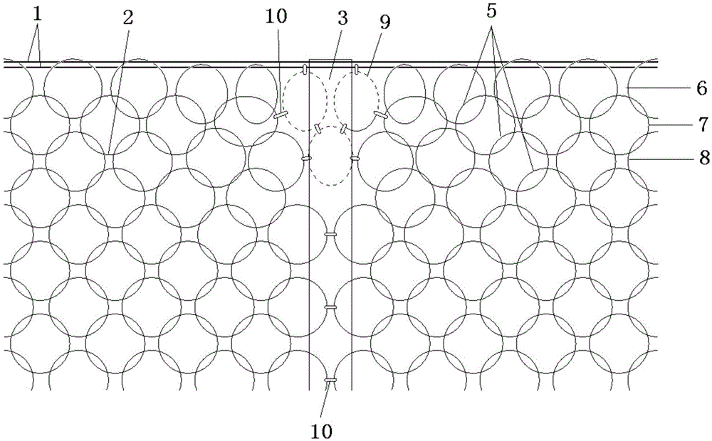
[0034] Such as image 3 As shown, the difference between this embodiment and Embodiment 2 is that two sets of top support ropes 1 are horizontally deployed on the top of the end support column and the middle support column 3, wherein only one set of top support rope 1 is connected with two additional meshes 9. Connecting pieces 10 are used to connect the additional meshes 9 and between the additional meshes 9 and the second row of meshes 7 and the third row of meshes 8 .
PUM
 Abstract
Description
Claims
Application Information
 - R&D
- Intellectual Property
- Life Sciences
- Materials
- Tech Scout
- Unparalleled Data Quality
- Higher Quality Content
- 60% Fewer Hallucinations
Browse by: Latest US Patents, China's latest patents, Technical Efficacy Thesaurus, Application Domain, Technology Topic, Popular Technical Reports.
© 2025 PatSnap. All rights reserved.Legal|Privacy policy|Modern Slavery Act Transparency Statement|Sitemap|About US| Contact US: help@patsnap.com


