Flexible barrier with additional connection structure

A technology for connecting structures and flexible nets, applied in infrastructure engineering, protective equipment, excavation, etc., to optimize load distribution, reduce replacement or maintenance requirements, and improve cost performance

Active Publication Date: 2018-09-04
布鲁克(苏州)工程有限公司
View PDF3 Cites 1 Cited by
  • Summary
  • Abstract
  • Description
  • Claims
  • Application Information

AI Technical Summary

Problems solved by technology

It has been proved that the above three schemes are effective in practical application, but there is still the possibility of further improvement and substitution

Method used


Image

  • Flexible barrier with additional connection structure
  • Flexible barrier with additional connection structure
  • Flexible barrier with additional connection structure

Examples


Embodiment 1

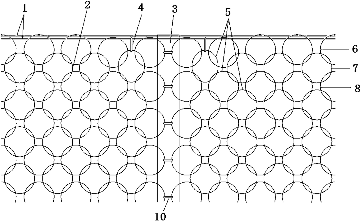
[0030] Such as figure 1 As shown, the top of the end support column and the middle support column 3 are horizontally deployed with two sets of top support ropes 1 , and two adjacent flexible metal meshes 2 are connected by connecting pieces 10 near the middle support column 3 . At the support node where the top support rope 1 intersects with the middle support column 3, the two mesh holes next to the middle support column 3 in the second row of mesh holes 7 of the metal flexible net 2 are added through the connecting ring 4 and a set of top support rope 1. At the same time, the four edge meshes 6 nested with the two secondary row meshes 7 are also connected to the group of top support ropes 1, and other edge meshes 6 of the metal flexible mesh 2 are connected with another Set the top support rope to 1 connection.

Embodiment 2

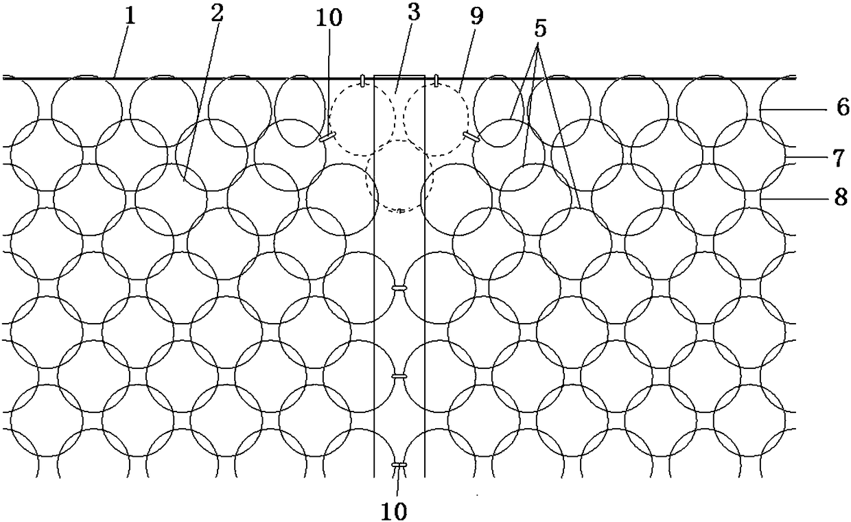
[0032] Such as figure 2 As shown, there is only one group of top support ropes 1 horizontally deployed on the top of the end support column and the middle support column 3, and the edge meshes 6 of the metal flexible net 2 are all connected with the top support rope 1. Three additional meshes 9 are added at the support node where the top support rope 1 intersects with the middle support column 3, wherein two additional meshes 9 are respectively connected to the top support rope 1 and the second row of mesh holes 7 through the connector 10. Two connections adjacent to the middle support column 3. Another additional mesh 9 is socketed with the above two additional meshes 9, and is socketed with two of the three rows of meshes 8 of the metal flexible mesh 2 that are closest to the middle support column 3.

Embodiment 3

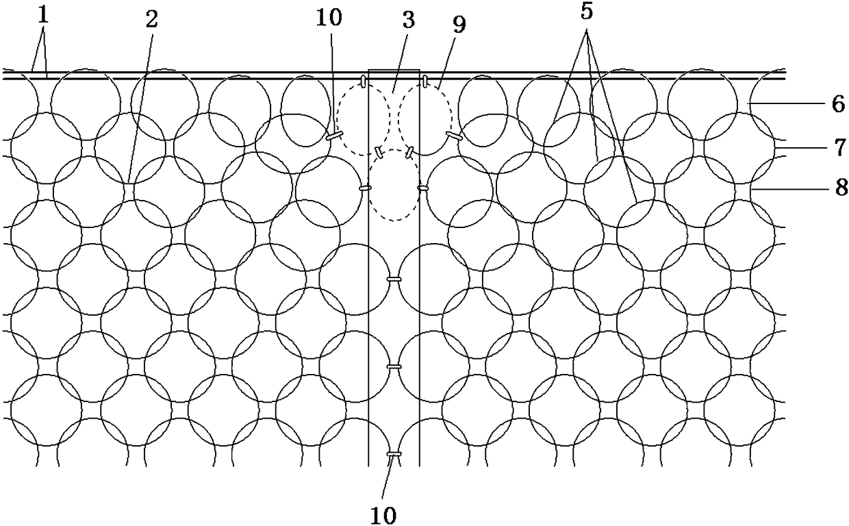
[0034] Such as image 3 As shown, the difference between this embodiment and Embodiment 2 is that two sets of top support ropes 1 are horizontally deployed on the top of the end support column and the middle support column 3, wherein only one set of top support rope 1 is connected with two additional meshes 9. Connecting pieces 10 are used to connect the additional meshes 9 and between the additional meshes 9 and the second row of meshes 7 and the third row of meshes 8 .


PUM


Abstract

The invention discloses a flexible blocking net, relates to a protective structure, and provides a flexible blocking net capable of optimizing load distribution and reducing local load concentrating. The flexible blocking net comprises two end supporting columns, a middle supporting column located between the two end supporting columns, a top supporting rope and a metal flexible net body, wherein the top supporting rope and the metal flexible net body are transversely unfolded to be arranged between the two end supporting columns. The top supporting rope is supported by the end supporting columns and the middle supporting column, and a supporting joint is arranged at the portion where the top supporting rope and the middle supporting column intersect with each other. The metal flexible net body comprises a plurality of net holes formed in rows, the row of net holes located at the edge of the metal flexible net body are edge net holes, and the several rows of net holes close to the edge net holes are edge-adjacent net holes. The edge net holes are connected with the top supporting rope in a slideable mode. The edge-adjacent net holes close to the supporting joint are connected with the top supporting rope in a slideable mode through the additional connecting structure. The flexible blocking net can be used for blocking movement objects and particularly can be used for blocking tumbling stone, sliding rock and earth masses, mud-rock flow, snow slide and blasting flying rock.

Description

technical field [0001] The invention relates to a protective structure, that is, a flexible blocking net for blocking moving objects, especially rolling stones, sliding rock and soil bodies, debris flows, avalanches and blasting flying stones. Background technique [0002] The flexible retaining net composed of various flexible nets, support ropes, support columns and their bases, pull ropes, and energy dissipation devices with overload protection has been widely used because of its good impact resistance and quick and convenient construction and installation. It is widely used in the construction or operation protection of highways, railways, hydropower stations, etc., to block and stop moving slope rolling rocks, sliding rock and soil bodies, debris flows, avalanches and blasting flying rocks, etc., or to change and Control the motion path and motion range of these moving objects, and have achieved good results. [0003] At present, among the various types of known flexib...

Claims


Application Information

Patent Timeline
Patent Type & Authority Patents(China)
IPC IPC(8): E01F7/04E02D17/20
CPCE01F7/045E02D17/202E02D2300/0026
Inventor 阳友奎
Owner 布鲁克(苏州)工程有限公司
Why Eureka
Try Eureka