Multifunctional cleaning mechanism for city cleaning

A cleaning mechanism and multi-functional technology, applied in road cleaning, cleaning methods, construction, etc., can solve the problems of single function and inflexible adjustment, and achieve the effect of diverse functions and flexible adjustment.

Active Publication Date: 2016-05-11
DONGFENG LIUZHOU MOTOR
7 Cites 20 Cited by

AI-Extracted Technical Summary

Problems solved by technology

[0005] The purpose of the present invention is to provide a multi-functional cleaning mechanism for urban cleaning, ther...

Method used

Fig. 1 has shown the structural representation of a kind of multifunctional cleaning mechanism for urban cleaning according to a preferred embodiment of the present invention, this multifunctional cleaning mechanism for urban cleaning comprises support 1, horizontal cleaning brush 2 and two A side cleaning brush 3, with reference to Fig. 1, the rear end of bearing 1 is provided with a connection seat 11 that is connected with manipulator, so that mechanism can be operated by manipulator, so that realize by vehicle-mounted cleaning. The horizontal cleaning brush 2 comprises a horizontal brush base 21, a horizontal brush shaft (not shown), a horizontal brush plate 22 and a horizontal bristle 23, the horizontal brush base 21 is arranged on the front end of the support 1, and the upper end of the brush plate rotating shaft is rotatable. Set on the horizontal brush base 21, the brush plate rotating shaft is driven to rotate by a brush plate rotating mechanism. Preferably, the brush plate rotating mechanism is a brush plate motor 26 arranged on the horizontal brush base 21, and the brush plate motor 26 passes through a transmission 27 is connected with the upper end of the brush plate rotating shaft. The horizontal brush plate 22 is fixedly sleeved on the lower end of the brush plate rotating shaft, and the bottom surface of the horizontal brush plate 22 is provided with horizontal bristles 23 . The brush plate motor 26 of the horizontal cleaning brush 2 drives the brush plate rotating shaft to rotate to drive the horizontal brush plate 22 to rotate, and the horizontal brush plate 22 can carry out the cleaning work through the horizontal bristles 23 . Preferably, the horizontal brush holder 21 is arranged at the front end of the support 1 in a manner that can be lifted up and down, so as to be able to flexibly adjust the height of the horizontal bristles 23 and improve the applicability. Further preferably, the front end of the support 1 is provided with a guide rail plate 12 extending downward, and the guide rail plate 12 is provided with a plurality of positioning holes 13 from top to bottom, and the horizontal brush holder 21 is sleeved in a liftable manner through a chute 24 on t...

Abstract

The invention discloses a multifunctional cleaning mechanism for city cleaning. The multifunctional cleaning mechanism comprises a support, a horizontal cleaning brush, and two side cleaning brushes, wherein the support is provided with a connecting seat which is connected with a manipulator, the horizontal cleaning brush comprises a horizontal brush holder arranged at the front end of the support, a brush plate rotating shaft of which the upper end is arranged on the horizontal brush holder, and driven to rotate by a brush plate rotating mechanism, a horizontal brush plate arranged at the lower end of the brush plate rotating shaft in a sleeving manner, and horizontal brush bristles arranged at the bottom surface of the horizontal brush plate; the two side cleaning brushes are symmetrically arranged on the left side and the right side of the support, and each side cleaning brush comprises a side brush rack of which one end is hinged to the support and driven to swing by a swing mechanism, a side brush shaft arranged on the side brush rack and driven to rotate by a brush shaft rotating mechanism, and side brush bristles, and the side brush shaft is provided with multiple rows of the side brush bristles arranged uniformly in the circumferential direction. The multifunctional cleaning mechanism disclosed by the invention can be applied to cleaning guardrails, roads, walls and billboards, and are diverse in functions and flexible to adjust.

Application Domain

Technology Topic

Image

  • Multifunctional cleaning mechanism for city cleaning

Examples

  • Experimental program(1)

Example Embodiment

[0017] The specific embodiments of the present invention will be described in detail below in conjunction with the drawings, but it should be understood that the protection scope of the present invention is not limited by the specific embodiments.
[0018] Unless otherwise expressly stated otherwise, throughout the specification and claims, the term "comprising" or its transformations such as "comprising" or "including" will be understood to include the stated elements or components, and not Other elements or other components are not excluded.
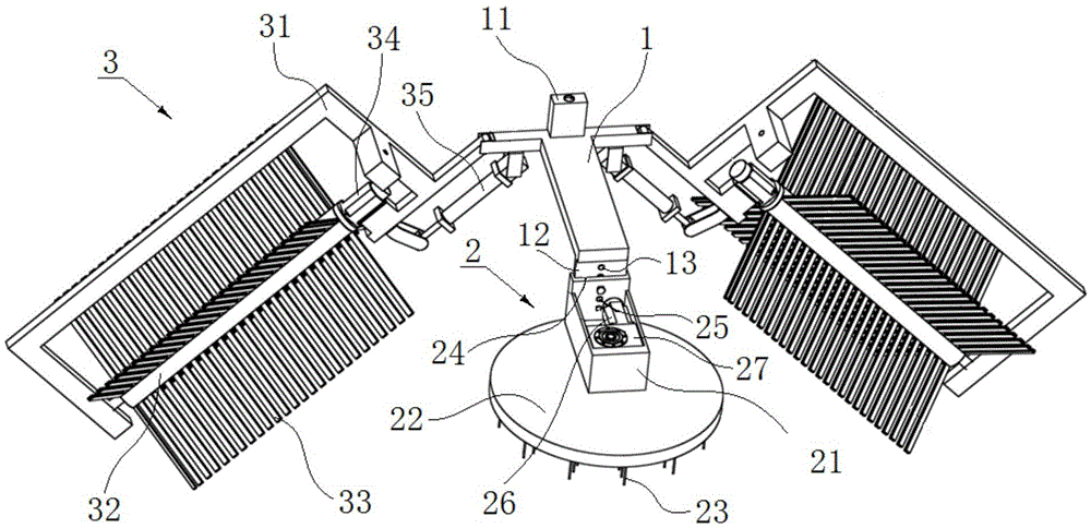
[0019] figure 1 Shows a structural schematic diagram of a multifunctional cleaning mechanism for city cleaning according to a preferred embodiment of the present invention. The multifunctional cleaning mechanism for city cleaning includes a support 1, a horizontal cleaning brush 2 and two side cleaning brushes 3 ,reference figure 1 , The rear end of the support 1 is provided with a connecting seat 11 connected with the manipulator, so that the mechanism can be operated by the manipulator, so as to realize the cleaning by the vehicle. The horizontal cleaning brush 2 includes a horizontal brush holder 21, a horizontal brush shaft (not shown in the figure), a horizontal brush plate 22 and horizontal bristles 23. The horizontal brush holder 21 is arranged at the front end of the holder 1, and the upper end of the brush plate rotating shaft is rotatable. Set on the horizontal brush holder 21, the brush plate rotating shaft is driven to rotate by a brush plate rotating mechanism. Preferably, the brush plate rotating mechanism is a brush plate motor 26 arranged on the horizontal brush holder 21. The brush plate motor 26 passes through a transmission 27 is connected with the upper end of the rotating shaft of the brush plate. The horizontal brush plate 22 is fixedly sleeved on the lower end of the brush plate rotating shaft, and the bottom surface of the horizontal brush plate 22 is provided with horizontal bristles 23. The brush plate motor 26 of the horizontal cleaning brush 2 drives the brush plate rotating shaft to rotate to drive the horizontal brush plate 22 to rotate, and the horizontal brush plate 22 can perform cleaning work through the horizontal bristles 23. Preferably, the horizontal brush holder 21 is arranged at the front end of the holder 1 in a manner capable of lifting, so as to be able to flexibly adjust the height of the horizontal bristles 23 and improve the applicability. Further preferably, the front end of the support 1 is provided with a downwardly extending guide plate 12, the guide plate 12 is provided with a plurality of positioning holes 13 from top to bottom, and the horizontal brush holder 21 is sleeved in a manner capable of lifting through a chute 24 On the rail plate 12, the horizontal brush holder 21 can slide up and down along the rail plate 12. The sliding groove 24 is provided with a connecting hole 25 corresponding to the positioning hole 13. The connecting hole 25 and the positioning hole 13 are connected by bolts. When the horizontal brush holder 21 is adjusted to a proper height, it can be locked by bolts fixed.
[0020] Continue to refer figure 1 , The two side cleaning brushes 3 are symmetrically arranged on the left and right sides of the support 1. Each side cleaning brush 3 includes a side brush holder 31, a side brush shaft 32 and a side brush 33. One end of the side brush holder 31 can swing up and down The side brush holder 31 is driven by a swing mechanism to swing, so that the tilt angle of the side brush holder 31 can be adjusted by the swing mechanism. Preferably, the swing mechanism is a swing hydraulic cylinder 35, the cylinder body of the swing hydraulic cylinder 35 is hinged on the support 1, and the piston rod of the swing hydraulic cylinder 35 is hinged on the side brush holder 31. The side brush shaft 32 is rotatably arranged on the side brush holder 31. The side brush holder 31 can be U-shaped. Both ends of the side brush shaft 32 are rotatably sleeved on one end of the opening of the side brush holder 31. . The side brush shaft 32 is driven to rotate by a brush shaft rotation mechanism. Preferably, the brush shaft rotation mechanism is a brush shaft motor 34 arranged on the side brush holder 31, and the brush shaft motor 34 is connected to one end of the side brush shaft 32. The side brush shaft 32 is evenly provided with several rows of side brush bristles 33 along the circumferential direction. When the brush shaft motor 34 drives the side brush shaft 32 to rotate, the side brush shaft 32 can drive the side brush bristles 33 for cleaning.
[0021] The structure of the present invention is simple and easy to use. During the cleaning process, a water spray system can be additionally provided through the vehicle-mounted system to spray water or cleaning liquid to the side cleaning brush 3 or the horizontal cleaning brush 2, or the nozzle of the water spray system Integrated installation on the support 1. When the two side cleaning brushes 3 swing the two side brush shafts 32 to the inclined or vertical position through the swing mechanism, the horizontal bristles 23 and the side bristles 33 form a U-shaped cleaning surface, combined with the action of the robot, the present invention The two side cleaning brushes 3 and the horizontal cleaning brush 2 can clean both sides and the top of the guardrail at the same time. There is no need to clean both sides of the guardrail separately, so as to shorten the driving distance and improve the cleaning efficiency. Moreover, since the inclination angle of the side cleaning side 3 and the height of the horizontal cleaning brush 2 can be adjusted, the present invention can clean guardrails of different widths. When the two side cleaning brushes 3 are placed in a horizontal position and the height of the horizontal cleaning brush 2 is adjusted, the side bristles 33 and the horizontal bristles 23 form a horizontal cleaning surface. Combined with the action of the manipulator, the present invention can pass Two side cleaning brushes 3 and horizontal cleaning brushes 2 clean roads, walls, billboards, etc. The present invention has multiple functions and flexible adjustment, and can realize one thing with multiple uses, and to a certain extent avoid resource waste. In addition, the side bristles 33 and the horizontal bristles 23 can be arranged to be removable, so that the brushes of different materials can be replaced according to the cleanliness of the road surface or the railing, which is convenient and practical.
[0022] The foregoing description of specific exemplary embodiments of the present invention is for the purpose of illustration and illustration. These descriptions are not intended to limit the invention to the precise form disclosed, and it is obvious that many changes and changes can be made based on the above teachings. The purpose of selecting and describing the exemplary embodiments is to explain the specific principles of the present invention and its practical application, so that those skilled in the art can realize and use various exemplary embodiments of the present invention and various different Choice and change. The scope of the present invention is intended to be defined by the claims and their equivalents.

PUM

no PUM

Description & Claims & Application Information

We can also present the details of the Description, Claims and Application information to help users get a comprehensive understanding of the technical details of the patent, such as background art, summary of invention, brief description of drawings, description of embodiments, and other original content. On the other hand, users can also determine the specific scope of protection of the technology through the list of claims; as well as understand the changes in the life cycle of the technology with the presentation of the patent timeline. Login to view more.

Similar technology patents

Surrounding rock stress analysis method of arbitrarily excavated cross section tunnels

ActiveCN102982247AVersatileHigh engineering reliabilitySpecial data processing applicationsGeophysicsMechanical models
Owner:杭州鑫高科技有限公司

Electrostatic spinning device with spinning nozzle capable of doing linear reciprocating motion

InactiveCN102817089AVersatileConcentration and orderliness of textile distributionNew-spun product collectionFilament/thread formingElectrospinningInjector
Owner:QINGDAO UNIV

Classification and recommendation of technical efficacy words

  • Versatile
  • Flexible adjustment

Tubular bus-bar fixing fitting

Owner:STATE GRID CORP OF CHINA +1
Why Eureka
Try Eureka