
Speed reduction mechanism

A technology of a reduction mechanism and a base, applied in the aerospace field, can solve the problems of poor transmission effect, poor connection structure stability, low integration, etc., and achieve the effects of stable and fast power transmission, stable connection structure, and high-precision output.

Inactive Publication Date: 2016-05-11
ZHENJIANG XINHANG PRECISION CASTING CO LTD
View PDF5 Cites 0 Cited by
  • Summary
  • Abstract
  • Description
  • Claims
  • Application Information

AI Technical Summary

Problems solved by technology

[0002] As we all know, the aerospace technology field has very strict quality requirements for products. When the reducer in the prior art is used on high-precision equipment such as aircraft or radar, it will be greatly worn after a period of use, resulting in high precision. decline, such as poor transmission effect, etc., the reason is that the internal structure design is complex and the integration level is low, resulting in poor stability of the connection structure and affecting the transmission efficiency

Method used


Image

  • Speed reduction mechanism
  • Speed reduction mechanism

Examples


Embodiment

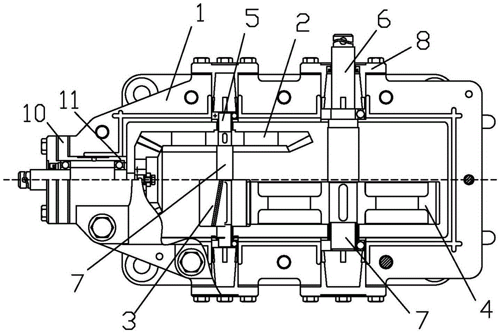
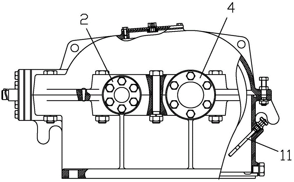
[0019] A deceleration mechanism, comprising a base 1, a gear 1 2 and a gear 2 3 are arranged in the base 1, and the gear 1 2 and the gear 2 3 are staggered and distributed, such as figure 1 As shown in the figure, the position height of the gear one 2 is higher than the position of the gear two 3, please refer to figure 2 At the same time, the diameter of the first gear 2 is smaller than the diameter of the second gear 3, and the transmission ratio can be changed by using the sizes of different gears, thereby realizing the deceleration function.

[0020] In this embodiment, the first gear 2 is sleeved on the shaft one 5, the position of the gear one 2 can be positioned by the shaft one 5, and the gear one 2 can be connected to the shaft one 5 At the same time, the top and bottom ends of the first shaft 5 are connected to the machine base 1 through the bearing end cover 8, and the position of the first shaft 5 can be determined by using the bearing end cover 8. , so that the ...


PUM


Abstract

The invention discloses a speed reduction mechanism. The speed reduction mechanism comprises a stand; a gear 1 and a gear 2 are arranged in the stand; the gear 1 coats a shaft 1; the top end and the bottom end of the shaft 1 are connected with the stand through bearing end covers; a gear 3 is additionally arranged on the shaft 1, is combined with the gear 2, and is perpendicularly positioned below the gear 1; the gear 2 coats a shaft 2; the top end and the bottom end of the shaft 2 are connected with the stand through bearing end covers; and a transmission shaft is arranged on the stand, and is engaged with the gear 1. The speed reduction mechanism can realize high-precision power output, and is higher in market value.

Description

technical field [0001] The invention relates to the field of aerospace technology, in particular to a deceleration mechanism, which can be used for aircraft or radar. Background technique [0002] As we all know, the field of aerospace technology has very strict requirements on the quality of products. When the reducer in the prior art is used in high-precision equipment such as aircraft or radar, after a period of use, there will be a large amount of wear and tear, resulting in high accuracy. For example, the transmission effect is not good. The reason is that the internal structure design is complex and the integration degree is low, resulting in poor stability of the connection structure and affecting the transmission efficiency. SUMMARY OF THE INVENTION [0003] In order to solve the above technical problems, we propose a deceleration mechanism for the purpose of lifting by changing the internal structure. [0004] For achieving the above object, technical scheme of t...

Claims


Application Information

Patent Timeline
Patent Type & Authority Applications(China)
IPC IPC(8): F16H1/20
CPCF16H1/20
Inventor 洪保平张洁
Owner ZHENJIANG XINHANG PRECISION CASTING CO LTD
Learn More