
LED lens emitting light from plane and design method of LED lens

A LED lens and plane technology, applied in the field of systems or instruments, and optical components, can solve problems such as difficult cleaning and low light output efficiency of LED lenses, and achieve the effects of easy cleaning, maintaining optical performance, and improving driving safety

Inactive Publication Date: 2016-05-11
CECEP LATTICELIGHTING
View PDF7 Cites 6 Cited by
  • Summary
  • Abstract
  • Description
  • Claims
  • Application Information

AI Technical Summary

Problems solved by technology

[0004] In order to solve the problems of low light-emitting efficiency and difficult cleaning of existing LED lenses, the present invention proposes a new type of planar light-emitting LED lens and its design method

Method used


Image

  • LED lens emitting light from plane and design method of LED lens
  • LED lens emitting light from plane and design method of LED lens
  • LED lens emitting light from plane and design method of LED lens

Examples


Embodiment Construction

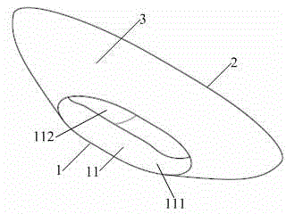
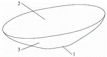
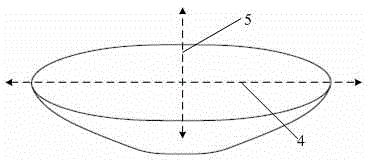
[0027] See attached Figures 1 to 3 , a planar light-emitting LED lens, comprising a top, a side and a bottom 1, characterized in that: the top is a light-emitting surface 2, the side is surrounded by a reflective cup surface 3, the bottom 1 is provided with an inner concave cavity 11, and the light-emitting surface 2 is The inner concave cavity 11 includes a top surface and a draft surface 111 , and the top surface is a free-form surface 112 .

[0028] Further, the reflective cup surface 3 is arranged around the side, so that the light that does not enter the lens from the free-form surface 112 passes through the reflective cup 3 and then emerges from the plane light-emitting surface 2 on the top, reducing the total reflection of the outgoing surface and improving the light-emitting efficiency of the lens.

[0029] Further, the lens includes two light transmission paths, the first transmission path is: a part of the light is refracted into the lens through the free-form surfa...


PUM


Abstract

The invention discloses an LED lens emitting light from a plane and a design method of the LED lens. The LED lens comprises a top, a side and a bottom, wherein a light emitting surface is arranged at the top; a reflector cup surface is arranged around the side; an inner concave is formed in the bottom. The light emitting surface is a plane. The inner concave comprises a top surface and a draft surface. The top surface is a free curved surface. The LED lens comprises two light transmitting paths, wherein one light transmitting path is that a part of light is refracted into the lens through the free curved surface, and is emitted from the light emitting surface after being propagated in the lens, that is, the light transmitting path is that light is transmitted from the free curved surface to the light emitting surface; and the other light transmitting path is that a part of light is refracted in the lens through the draft surface, is reflected through the reflector cup surface, and is finally emitted after being refracted at the light emitting surface, that is, the light transmitting path is that light is transmitted from the draft surface to the reflector cup surface, and then is transmitted from the reflector cup surface to the light emitting surface. The LED lens has the advantages that the light emitting surface is the plane, so that the maintenance convenience of a lamp is improved greatly, and after dust is accumulated on the surface of the lens, the surface of the lens can be easily cleaned, so that the lamp is higher in maintaining coefficient, and the lens keeps high good optical performance.

Description

technical field [0001] The invention belongs to the technical field of optical components, systems or instruments, and specifically refers to a planar light-emitting LED lens and a design method thereof. Background technique [0002] Compared with traditional lighting sources, LED has the advantages of energy saving, environmental protection, long service life, and fast response. It is considered to be the best light source in the 21st century. The development, development, and production of LED lighting products have become a very attractive sunrise industry. However, the light emitted by LEDs has a Lambertian distribution, so it is difficult to be directly used for lighting. Secondary optical design is required, and different lighting scenarios have different requirements. The packaging of LED chips is regarded as an optical design, and the optical design process of designing refracting lenses and reflectors to meet lighting applications is regarded as a secondary optical ...

Claims


Application Information

Patent Timeline
IPC IPC(8): F21V5/04F21Y101/02
Inventor 程治明张志海罗茶根洪芸芸
Owner CECEP LATTICELIGHTING
Learn More