Testing method for lightning arrester of transformer station in power grid

A test method and lightning arrester technology, applied in the field of lightning arresters, can solve problems such as mechanical vibration load damage, potential safety hazards, and high labor intensity of workers, so as to achieve the effect of solving safety problems and improving safety performance

Inactive Publication Date: 2016-05-11
STATE GRID CORP OF CHINA +1
View PDF4 Cites 2 Cited by
  • Summary
  • Abstract
  • Description
  • Claims
  • Application Information

AI Technical Summary

Problems solved by technology

[0003] The arrester itself in use will be affected by its own gravity, and at the same time it will bear the recombination generated by wind pressure. Due to the wind and other external forces, the wind vibration response will cause the arrester itself to be subjected to mechanical vibration loads. Damage due to excessive vibration load
[0004] In addition, in order to ensure the normal use of the arrester, it is necessary to regularly detect the current leakage of the arrester. The traditional test plan for the current leakage of the arrester requires bucket trucks, elevators and many operators. The labor intensity of the workers is high, and there are potential safety hazards.

Method used


Image

  • Testing method for lightning arrester of transformer station in power grid
  • Testing method for lightning arrester of transformer station in power grid

Examples


Embodiment 1

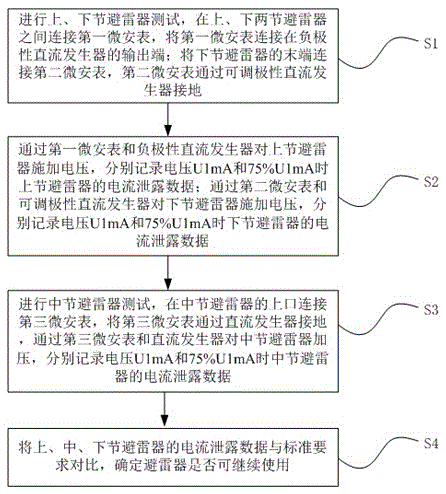
[0026] like figure 1 As shown, the method for testing the lightning arrester in the substation in the network provided by this embodiment includes the steps of testing the leakage current of the lightning arrester and the step of detecting the life of the lightning arrester; wherein, the testing steps of the leakage current of the lightning arrester include:

[0027] Step S1, carry out the test of the upper and lower lightning arresters, connect the first microammeter between the upper and lower lightning arresters, and connect the first microammeter to the output terminal of the negative polarity DC generator; connect the end of the lower lightning arrester Connect the second microammeter, and the second microammeter is grounded through the adjustable polarity DC generator;

[0028] Step S2, applying voltage to the upper surge arrester through the first microammeter and the negative polarity DC generator, respectively recording the current leakage data of the upper surge arre...

Embodiment 2

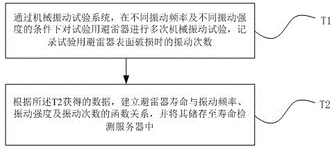
[0035] like figure 2 As shown, in the test method for the arrester in the substation in the network provided by this embodiment, the steps for detecting the life of the arrester are specifically as follows:


PUM


Abstract

The invention provides a testing method for a lightning arrester of a transformer station in a power grid, wherein the testing method comprises a testing step of testing leakage current of the lightning arrester and a step of testing service life of the lightning arrester. Through testing the leakage current of the lightning arrester, whether the leakage current of the lightning arrester is in a normal range can be determined in time, thereby facilitating lightning arrester maintenance in time, and improving safety performance of the lightning arrester in the use process. Furthermore, through arranging a sensor on the lightning arrester, vibration data of the lightning arrester can be acquired in real time. Through utilizing a function relationship between the lightning arrester service life, the vibration frequency, the vibration strength and the number of vibrations, wherein the function relationship is acquired through mechanical vibration simulating tests, the service life state of the lightning arrester is monitored in real time, thereby replacing the lightning arrester in time and settling a safety problem caused by incapability of replacing damaged lightning arrester in long-term use.

Description

technical field [0001] The invention relates to the technical field of lightning arresters, in particular to a test method for lightning arresters in substations in a network. Background technique [0002] Surge arrester is one of the main protective devices to ensure the safe operation of power station equipment. Under normal system operating voltage, it presents a high resistance state, and only microampere current passes through it. Under the action of overvoltage and large current, its resistance drops sharply, and the leakage prevention Overvoltage energy, thereby limiting the voltage amplitude, to protect communication cables or equipment. [0003] The arrester itself in use will be affected by its own gravity, and at the same time it will bear the recombination generated by wind pressure. Due to the wind and other external forces, the wind vibration response will cause the arrester itself to be subjected to mechanical vibration loads. Damaged due to excessive vibrati...

Claims


Application Information

Patent Timeline
Patent Type & Authority Applications(China)
IPC IPC(8): G01R31/02G01R19/00G01M7/02
CPCG01M7/02G01R19/00G01R31/50
Inventor 刘冰
Owner STATE GRID CORP OF CHINA
Why Eureka
Try Eureka