

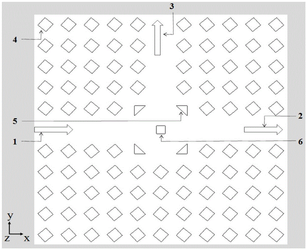
Right-angle output double-way inverted optical clock signal generator with photonic crystal T-type waveguide
A photonic crystal and clock signal technology, applied in the directions of light guides, optics, optical components, etc., can solve the problems of inability to use optical circuit integration, large volume, etc., and achieve the effects of large practical value, small structure and wide operating wavelength range.
- Summary
- Abstract
- Description
- Claims
- Application Information
AI Technical Summary
Problems solved by technology
Method used
Image

Examples
Embodiment 1
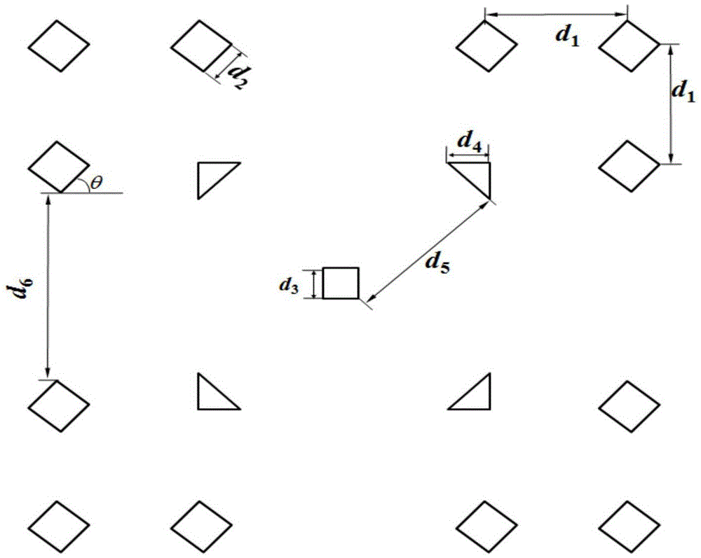
[0071] In this embodiment, the function of a two-way anti-phase optical clock signal generator at different wavelengths can be realized by changing the lattice constant in equal proportions without considering the dispersion or the dispersion of the material changes very little. Let parameter a=6.1772×10 -3 [m],d 2 =0.3a,d 3 =0.2817a,d 5 =1.2997a, μ=9.6125, p=0.7792, normalized light wave frequency ωa / 2πc=0.4121, other parameters remain unchanged, so that it corresponds to 20GHz light wave. refer to Figure 5 , the logic contrast in the band-gap optical frequency range is obtained through simulation calculation, and the structure has the function of high logic contrast and double-way anti-phase optical clock signal generator.
Embodiment 2
[0073] In this embodiment, the function of a two-way anti-phase optical clock signal generator at different wavelengths can be realized by changing the lattice constant in equal proportions without considering the dispersion or the dispersion of the material changes very little. Let parameter a=4.1181×10 -3 [m],d 2 =0.3a,d 3 =0.2817a,d 5 =1.2997a, μ=9.6125, p=0.7792, normalized light wave frequency ωa / 2πc=0.4121, other parameters remain unchanged, so that it corresponds to 30GHz light wave. refer to Figure 6 , the logic contrast in the band-gap optical frequency range is obtained through simulation calculation, and the structure has the function of high logic contrast and double-way anti-phase optical clock signal generator. pass Figure 6 It can be seen that when the normalized light wave frequency ωa / 2πc=0.4121, the logic contrast can reach 48dB.
Embodiment 3
[0075] In this embodiment, the function of the dual-channel anti-phase optical clock signal generator under different wavelength duty ratios can be realized by changing the lattice constant in equal proportions without considering the dispersion or the dispersion of the material changes very little. Let parameter a=3.0886×10 -3 [m],d 2 =0.3a,d 3 =0.2817a,d 5 =1.2997a, μ=9.6125, p=0.7792, normalized light wave frequency ωa / 2πc=0.4121, other parameters remain unchanged, so that it corresponds to 40GHz light wave. refer to Figure 7 , the logic contrast in the band-gap optical frequency range is obtained through simulation calculation, and the structure has the function of high logic contrast and double-way anti-phase optical clock signal generator.
[0076] pass Figure 8 It can be seen that when the normalized light wave frequency ωa / 2πc=0.4121, the light field simulation diagram obtained is calculated by the finite element software COMSOL. It can be observed that the TE ...
PUM
| Property | Measurement | Unit |
|---|---|---|
| refractive index | aaaaa | aaaaa |
| relative permittivity | aaaaa | aaaaa |
Abstract
Description
Claims
Application Information