Reflective phase shifter and method of phase shifting using a hybrid coupler with vertical coupling

a hybrid coupler and phase shifting technology, applied in the field of radiofrequency phase shifters, can solve the problem that the line-of-sight link between the transmitter and the receiver can easily be broken, and achieve the effect of reducing substrate loss, reducing differential implementation, and flexible setting of characteristic impedances

Active Publication Date: 2011-06-28
GLOBALFOUNDRIES US INC
View PDF3 Cites 17 Cited by
  • Summary
  • Abstract
  • Description
  • Claims
  • Application Information

AI Technical Summary

Benefits of technology

[0008]An integrated reflective-type differential phase shifter includes a vertical coupled line hybrid and inductive-capacitive (LC) resonant loads. The hybrid coupler includes differential coplanar striplines (CPS) placed one on top of the other using different metal layers so that the coupling occurs vertically. This reduces the employed area and allows an easier differential implementation. The widths of the CPS are not identical, this feature allows more flexibility to set their characteristic impedances. At a lower metal level (e.g. M1), metal strips are placed orthogonally with respect to the CPS as shielding to reduce the substrate loss. These metal strips are also designed to reduce the wave propagation speed in the CPS and reduce the overall size of the coupler. The reflective load terminations for the hybrid coupler are implemented with a parallel resonant LC circuit. The inductor sets the imaginary part of the reflective load impedance to a value where a change in capacitance yields a larger change in phase for the overall phase shifter. This structure is suitable for mmWave as the capacitive parasitic of the inductor can be absorbed into the shunt inductor value. The implementation features are suitable for integration in SiGe and CMOS technologies, and operation at mmWave frequencies.
[0009]In a differential embodiment. A hybrid coupler having differential coplanar striplines (CPS) placed one on top of the other using different metal layers so that the coupling occurs vertically is included. This reduces the employed area and allows an easier differential implementation. The widths of the CPS are not identical. This feature allows more flexibility to set their characteristic impedances. At a lower metal level (e.g. M1), metal strips are placed orthogonally with respect to the CPS as shielding to reduce the substrate loss. These metal strips are also designed to reduce the wave propagation speed in the CPS and reduce the overall size of the coupler.
[0010]In a single-ended embodiment: The coupler includes coupled lines placed over / under metal strips that are orthogonal to the coupled lines. The strips shield and improve coupling, isolation with smaller coupler size and higher characteristic impedance.
[0011]A method for phase shifting a transmitted signal includes distributing a signal to one or more antennae, phase shifting the signal by an amount dependent on a phase shifter associated with each antennae, the phase shifter including a hybrid coupler being ground shielded and reflective terminations connected to the hybrid coupler, wherein the reflective terminations include a parallel LC circuit and transmitting the phase shifted signals from the one or more antennae to provide spatial selectivity through phase shifted differences.

Problems solved by technology

In such an application, the line-of-sight link between the transmitter and receiver can easily be broken due to obstacles in the path.

Method used


Image

  • Reflective phase shifter and method of phase shifting using a hybrid coupler with vertical coupling
  • Reflective phase shifter and method of phase shifting using a hybrid coupler with vertical coupling
  • Reflective phase shifter and method of phase shifting using a hybrid coupler with vertical coupling

Examples


Embodiment Construction

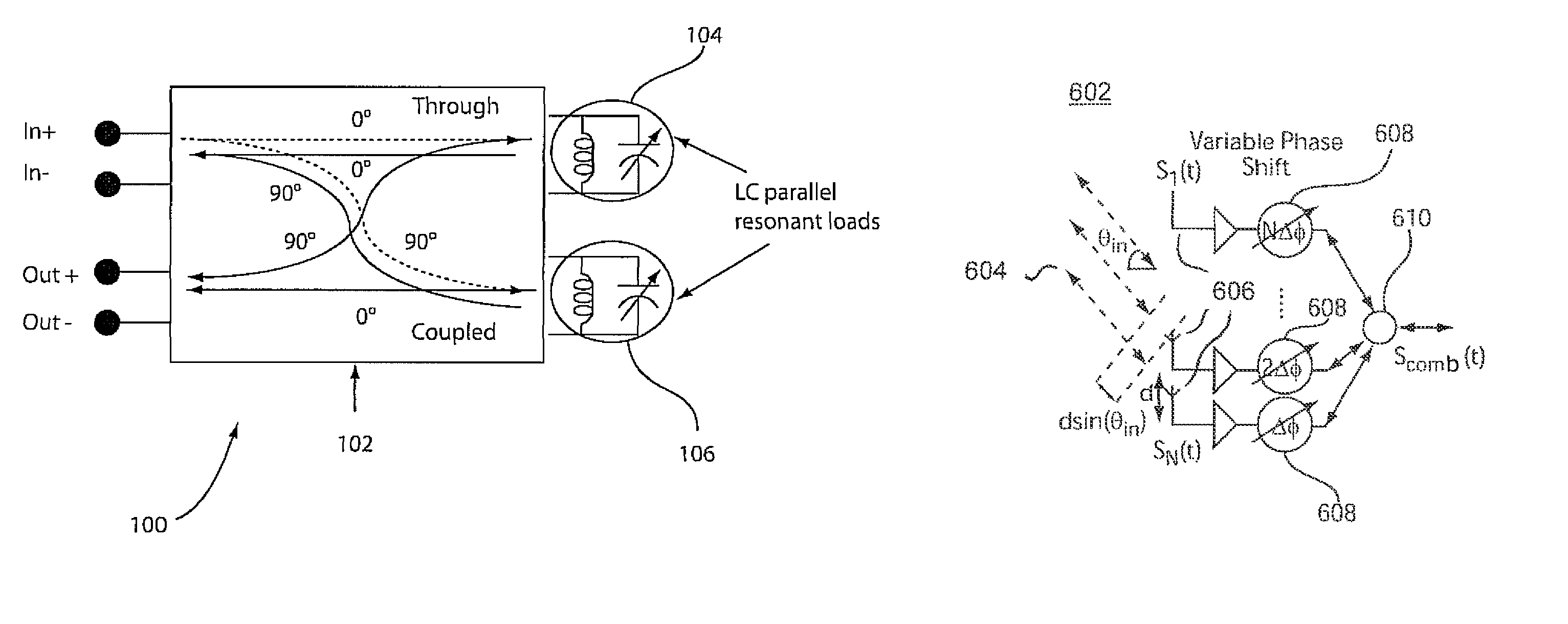
[0031]In accordance with the present principles, a ground-shielded coupled-line coupler is integrated with LC parallel resonant reflective loads to form a Reflection-type Phase Shifter (RTPS) which is suitable for a silicon implementation and operation at mmWave frequencies. Both, single-ended and differential embodiments are considered. A coupled-line coupler is chosen to provide a wider bandwidth of operation over other alternatives (e.g. branch-line coupler). Even mode and odd mode impedances that can be obtained with this coupler in an integrated implementation are adequate for a Reflection-type Phase Shifter (RTPS) at mmWave frequencies. In the differential case, the coupler in one embodiment includes differential coplanar striplines (CPS) placed one on top of the other using different metal layers so that the coupling occurs vertically. This reduces the employed area and permits an easier differential implementation. In the single-ended case, the coupler in accordance with one...


PUM


Abstract

A phase shifter and method include a hybrid coupler being ground shielded. The hybrid coupler with reflective terminations connected to the hybrid coupler is configured to phase shift an applied signal wherein the reflective terminations include a parallel LC circuit.

Description

BACKGROUND[0001]1. Technical Field[0002]The present invention relates to radio-frequency phase shifters and more particularly to phase shifters operating at millimeter-wave frequencies for integrated phased arrays systems.[0003]2. Description of the Related Art[0004]Phase sifters and phased arrays are now presented in a context which illustrates their requirements for monolithic integration and the existing implementations. Phased Array Systems: Phased array transceivers are a class of multiple antenna systems that achieve spatial selectivity through control of the time delay differences between successive antenna signal paths. A change in this delay difference modifies the direction in which the transmitted / received signals add coherently, thus “steering” the electromagnetic beam. The integration of phased-arrays in silicon-based technologies has aroused great interest in recent times due to potential applications in high-speed wireless communication systems and radar.[0005]There a...

Claims


Application Information

Patent Timeline
Patent Type & Authority Patents(United States)
IPC IPC(8): H01Q3/36H01P1/18
CPCH01P1/185H01P1/18
Inventor KRISHNASWAMY, HARISHNATARAJAN, ARUN SRIDHARGARCIA, ALBERTO VALDES
Owner GLOBALFOUNDRIES US INC
Why Eureka
Try Eureka