Omnibearing remote control detection equipment

A technology of remote control and detection equipment, which is applied in the direction of program control, computer control, general control system, etc., and can solve the problems of high requirements, loss, and inability to achieve real-time and continuous recording.

Inactive Publication Date: 2016-05-11
李明
View PDF0 Cites 0 Cited by
  • Summary
  • Abstract
  • Description
  • Claims
  • Application Information

AI Technical Summary

Problems solved by technology

[0002] At present, when the product is put into use and there is a failure that may lead to return, the processing method used is that the engineer in charge of the product handles it at close range on site. This method firstly because the failure problem cannot be dealt with in the first time, it often misses the remedy The best time to cause huge losses, this method is very demanding, the engineer

Method used


Image

  • Omnibearing remote control detection equipment

Examples


Embodiment Construction

[0008] Embodiments of the present invention will be described in detail below in conjunction with the accompanying drawings.

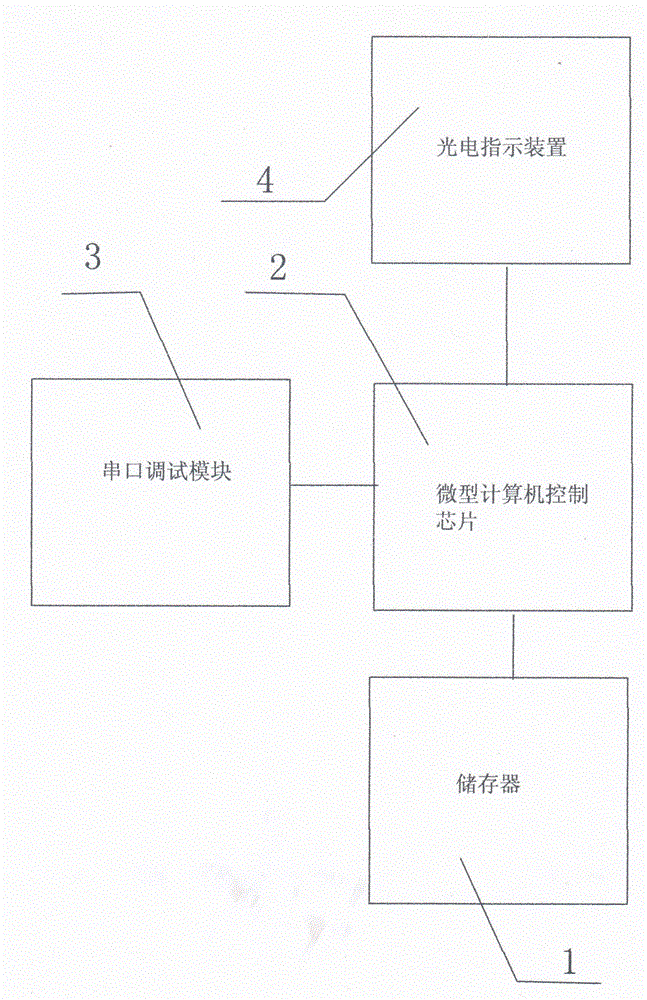
[0009] figure 1 is a structural diagram of an embodiment of the present invention, such as figure 1 As shown, the all-round remote control detection device of the present invention is electrically connected with the object to be debugged, a hard disk 1 for storing data information, a microcomputer 2 for controlling and processing the acquired data information, and a computer for connecting to the object to be debugged. A monitor 3 and a status indicator light 4 , the microcomputer 2 is electrically connected to the hard disk 1 , and the microcomputer 2 is electrically connected to the monitor 3 .

[0010] The microcomputer 2 and the hard disk 1 are bidirectionally electrically connected to obtain the data information in the hard disk 1, the microcomputer 2 is bidirectionally electrically connected to the monitor 3, the monitor 3 is connected to the ob...


PUM


Abstract

The invention discloses omnibearing remote control detection equipment. The equipment comprises a hard disk, a miniature calculator and a monitor used for connecting a debugged object. By using the equipment, a problem can be processed at first time; data can be recorded continuously in real time; a reliable basis is provided for fault problem determination and remote control can be achieved.

Description

technical field [0001] The invention relates to a debugging device, in particular to an all-round remote control detection device. Background technique [0002] At present, when the product is put into use and there is a failure that may lead to return, the processing method used is that the engineer in charge of the product handles it at close range on site. This method firstly because the failure problem cannot be dealt with in the first time, it often misses the remedy Optimum timing to cause huge losses is a human-intensive approach, and the engineers dispatched to the site must ensure that the failure is resolved. When random fatal failures occur during the product design process, the processing method used is to set up test platforms in large quantities, and special personnel to operate, simulate and monitor the resulting phenomena. Due to a certain lag in human operation, strict real-time and continuous testing cannot be achieved. Record. Contents of the invention ...

Claims


Application Information

Patent Timeline
IPC IPC(8): G05B19/042
Inventor 李明
Owner 李明
Why Eureka
Try Eureka