
Method for connecting converter to reluctance motor, control device and drive device

A technology of control device and reluctance motor, which is applied in the direction of AC motor control, electromechanical transmission control, motor control, etc., can solve the problem of not configuring the sensor of speed and/or commutation position, etc., and achieve the effect of simple cost

Active Publication Date: 2019-07-30
SIEMENS AG
View PDF5 Cites 0 Cited by
  • Summary
  • Abstract
  • Description
  • Claims
  • Application Information

AI Technical Summary

Problems solved by technology

Such reluctance motors are in most cases not equipped with sensors capable of measuring rotational speed and / or commutation position for cost reasons

Method used


Image

  • Method for connecting converter to reluctance motor, control device and drive device
  • Method for connecting converter to reluctance motor, control device and drive device
  • Method for connecting converter to reluctance motor, control device and drive device

Examples


Embodiment Construction

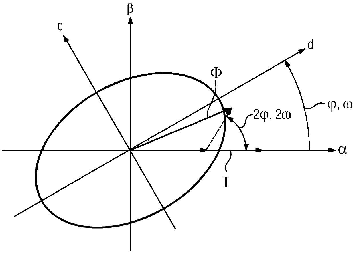
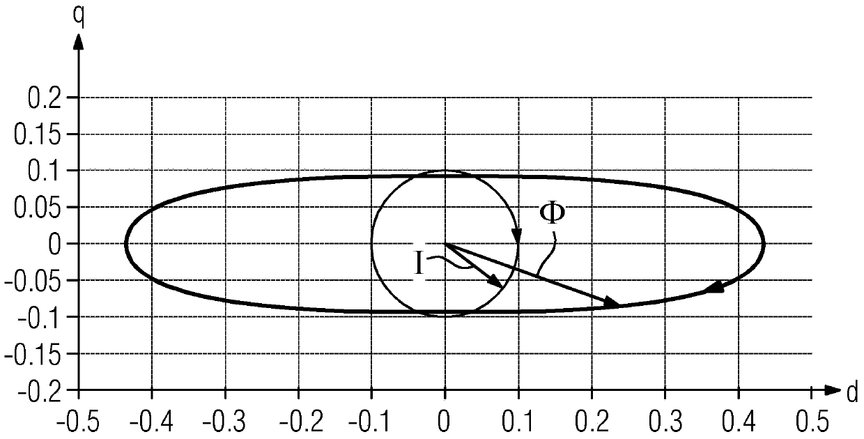
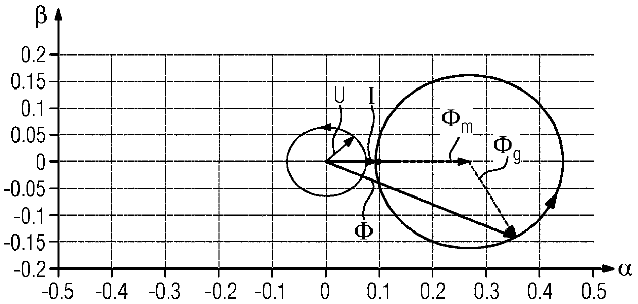
[0032] At present, the converter 6 should be connected with the rotating reluctance motor 2 at the correct speed and phase. In particular, the reluctance motor 2 is configured as a synchronous reluctance motor 2 without a damping cage. The reluctance motor 2 has a stator with corresponding stator windings 11, which is not currently shown. In addition, the reluctance machine 2 has a rotor, not shown here, which has a rotor lamination stack, which is configured to be magnetically anisotropic. The rotor lamination group can be formed by a stack of plates and have corresponding magnetic flux blocking members, that is, air-filled areas or gaps, thereby obtaining a magnetically anisotropic design.

[0033] figure 1 The space vector diagram of the reluctance motor 2 is shown. In this space vector diagram, the physical parameters of the reluctance motor 2 are shown as vectors in the complex plane. in figure 1 A stator coordinate system is shown in, which has an axis α and an axis β. ...


PUM


Abstract

The invention relates to a method for connecting a converter (6) to a rotating reluctance machine (2), wherein the reluctance machine (2) has a stator with a stator winding (11) and a A rotor of a magnetically anisotropic rotor lamination, the method being implemented by inputting a direct current (I) into a stator winding (11); determining a voltage (U) to be applied at the stator winding (11), the voltage Induced into the stator winding (11) by a change in the magnetic flux (Φ) due to the rotation of the rotor, and the rotor frequency (f ) and / or rotor angle ( ).

Description

Technical field [0001] The invention relates to a method for connecting a converter to a rotating reluctance motor. In addition, the invention relates to a control device for a converter of a reluctance motor. Finally, the invention relates to a drive device. Background technique [0002] Currently of interest are reluctance motors, especially synchronous reluctance motors without a shock cage. This type of synchronous reluctance motor without a damping cage, once it runs on the ground at the frequency converter, it can provide high dynamics at the same time, especially in the area of ​​partial load, it also has very good efficiency. . Unlike asynchronous motors, there is no constant value of rotor time that causes "interference" in the construction of dynamic magnetic flux. Therefore, synchronous reluctance motors provide advantages. They also have excellent energy efficiency when the magnetic flux decreases in the partial load area. The high load torque requirements should ...

Claims


Application Information

Patent Timeline
Patent Type & Authority Patents(China)
IPC IPC(8): H02P21/24H02P21/18H02P21/14H02P25/092H02P25/024
CPCH02P25/024H02P21/14H02P2207/05H02P1/465H02P6/182H02P6/185H02P25/08
Inventor 蒂洛·威格尔
Owner SIEMENS AG
Learn More