Method for connecting an inverter to a reluctance machine, control device and drive assembly
A reluctance motor and control device technology, which is applied in the direction of AC motor control, electromechanical transmission control, motor control, etc., can solve the problem of not configuring the sensor of speed and/or commutation position, etc., and achieve the effect of simple cost
- Summary
- Abstract
- Description
- Claims
- Application Information
AI Technical Summary
Problems solved by technology
Method used
Image
Examples
Embodiment Construction
[0032] The current converter 6 should now be connected to the rotating reluctance machine 2 with the correct speed and phase. The reluctance motor 2 is designed in particular as a synchronous reluctance motor 2 without a damper cage. The reluctance machine 2 has a stator (not shown here) with a corresponding stator winding 11 . Furthermore, the reluctance machine 2 has a rotor, not shown here, which has a laminated rotor core which is designed to be magnetically anisotropic. The rotor lamination stack can be formed from laminated cores and have corresponding flux locks, ie air-filled regions or openings, whereby a magnetically anisotropic design is achieved.
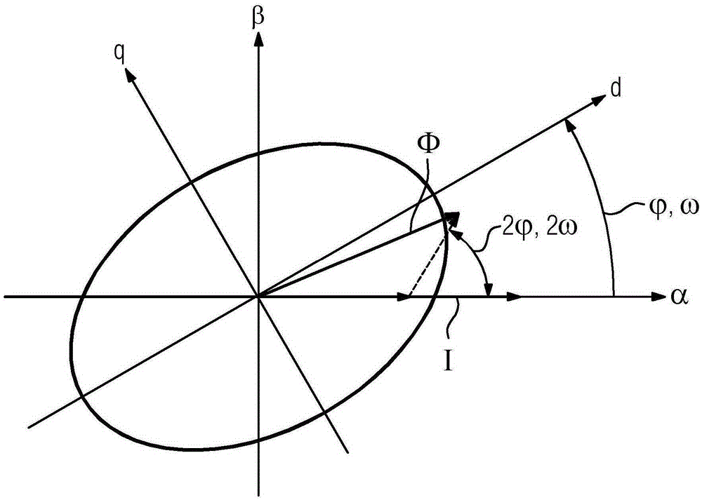
[0033] figure 1 The space vector diagram of the reluctance machine 2 is shown. In this space vector diagram, the physical variables of the reluctance machine 2 are shown as vectors in the complex plane. exist figure 1 The stator coordinate system is shown in , which has axis α and axis β. Axis α shows the real part...
PUM
 Abstract
Description
Claims
Application Information
 - R&D
- Intellectual Property
- Life Sciences
- Materials
- Tech Scout
- Unparalleled Data Quality
- Higher Quality Content
- 60% Fewer Hallucinations
Browse by: Latest US Patents, China's latest patents, Technical Efficacy Thesaurus, Application Domain, Technology Topic, Popular Technical Reports.
© 2025 PatSnap. All rights reserved.Legal|Privacy policy|Modern Slavery Act Transparency Statement|Sitemap|About US| Contact US: help@patsnap.com


