Image data z-axis coverage extension for tissue dose estimation

A technology of image data and coverage, applied in the field of image data processing, can solve problems such as inaccurate dose estimation and not reflecting the real geometric shape

Active Publication Date: 2016-05-11
KONINKLJIJKE PHILIPS NV
View PDF10 Cites 0 Cited by
  • Summary
  • Abstract
  • Description
  • Claims
  • Application Information

AI Technical Summary

Problems solved by technology

Unfortunately, this method does not reflect the true geometry of ...

Method used


Image

  • Image data z-axis coverage extension for tissue dose estimation
  • Image data z-axis coverage extension for tissue dose estimation
  • Image data z-axis coverage extension for tissue dose estimation

Examples


Embodiment Construction

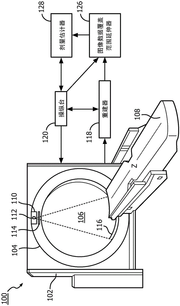
[0027] initial reference figure 1 , schematically illustrates an imaging system 100 such as a computed tomography (CT) scanner. In other embodiments, imaging system 100 includes another imaging modality that emits ionizing radiation, a therapeutic treatment device that emits ionizing radiation, and / or other devices that emit ionizing radiation.

[0028] The imaging system 100 includes a stationary gantry 102 and a rotating gantry 104 rotatably supported by the stationary gantry 102 . The rotating gantry 104 rotates about an examination region 106 about a longitudinal or z-axis ("Z"). A subject support 108 , such as a couch, supports a target or object in the examination region 106 . Object support 108 can be used to vertically and / or horizontally position an object or target relative to imaging system 100 before, during, and / or after scanning.

[0029] A radiation source 110 , such as an X-ray tube, is supported by the rotating gantry 104 and rotates with the rotating gantr...


PUM


Abstract

A method for extending initial image data of a subject for dose estimation includes obtaining first image data of the subject for dose calculation, wherein the first image data has a first field of view. The method further includes obtaining second image data for extending the field of view of the first image data. The second image data has a second field of view that is larger than the first field of view. The method further includes extending the first field of view based on the second image data, producing extended image data.

Description

technical field [0001] The following generally relates to image data processing, and more specifically to extending the volume of acquired image data to account for the calculation of dose to scanned tissue, and is described with a specific application to computed tomography (CT); however, the following also contemplates Other devices that emit ionizing radiation, such as x-ray imagers, radiation therapy equipment, and / or other devices. Background technique [0002] A CT scanner generally includes an x-ray tube mounted on a rotatable gantry opposite a detector array positioned across an examination region. The rotatable gantry and thus the x-ray tube rotates around the examination region and the x-ray tube emits ionizing radiation which traverses the examination region and parts of the object in said examination region. A detector array detects the radiation and generates projection data representative of the radiation. A reconstructor reconstructs the projection data, gen...

Claims


Application Information

Patent Timeline
IPC IPC(8): A61B6/00A61B6/10G01T1/02
CPCA61B6/10A61B6/14A61B6/488A61B6/5229A61B6/5235A61B6/5247A61B6/542A61N5/1031G06T7/30G06T2207/10081G06T2207/20221G16H30/40A61B6/032A61C9/0046A61C9/0053A61C9/006A61C9/0086G06T7/174G06T19/006G06T2210/41
Inventor H·鲁佩茨霍芬C·洛伦茨J·维格特P·普林森R·普罗克绍
Owner KONINKLJIJKE PHILIPS NV
Why Eureka
Try Eureka