Magnetic induction motor

A magnetic induction type, electric motor technology, applied in the direction of electric components, magnetic circuit rotating parts, magnetic circuit shape/style/structure, etc., to achieve the effect of suppressing cracks and avoiding contact

Active Publication Date: 2016-05-11
MITSUBISHI ELECTRIC CORP
View PDF5 Cites 5 Cited by
  • Summary
  • Abstract
  • Description
  • Claims
  • Application Information

AI Technical Summary

Problems solved by technology

However, the stator coils of the concentrated winding method are each composed of a plurality of concentrated winding coils produced by winding a conductive wire around one tooth without straddling the slots. The inner peripheral surface of the core back (coreback) protrudes radially inward and the stator core is formed by arranging teeth away from each other in the circumferential direction.

Method used


Image

  • Magnetic induction motor
  • Magnetic induction motor
  • Magnetic induction motor

Examples


Embodiment approach 1

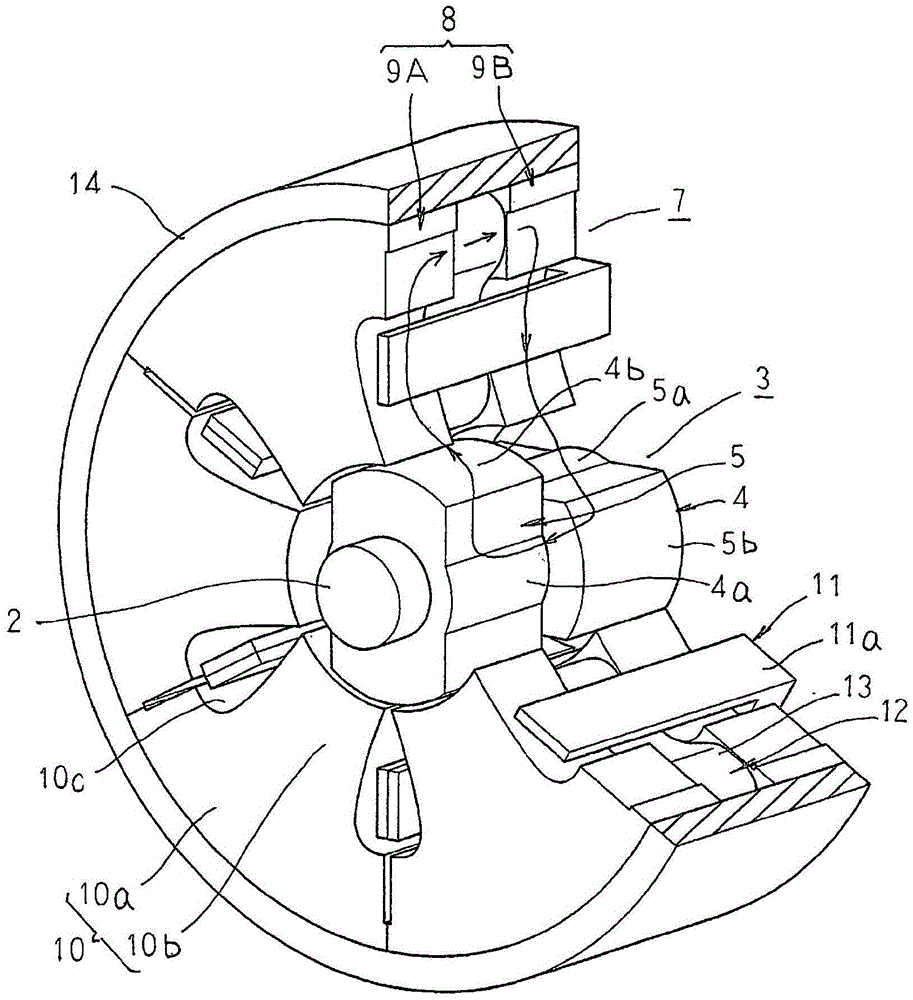
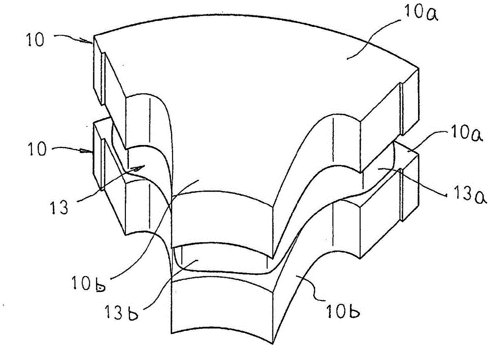
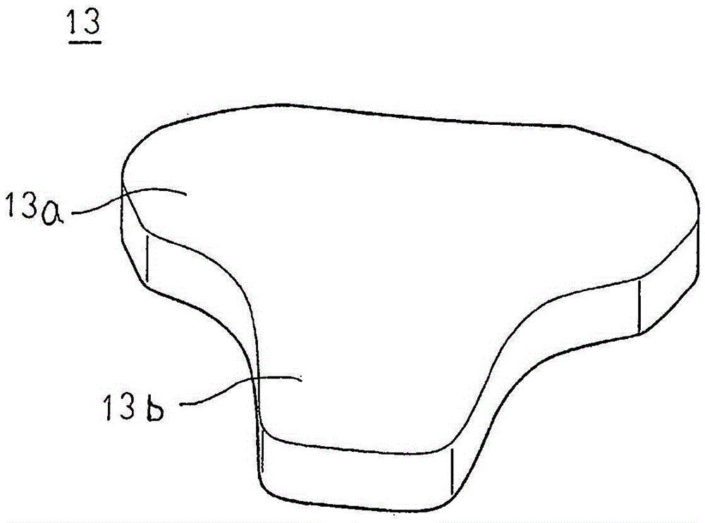
[0026] figure 1 is a partially cutaway perspective view showing the main structure of the magnetic induction motor according to Embodiment 1 of the present invention, figure 2 It is a perspective view showing core block pairs aligned in the axial direction in the magnetic induction motor according to Embodiment 1 of the present invention, image 3 It is a perspective view showing a magnet block in the magnetic induction motor according to Embodiment 1 of the present invention.

[0027] exist figure 1 Among them, the magnetic induction motor 1 includes a rotor 3 coaxially fixed to a rotating shaft 2 made of a block-shaped magnetic body such as iron, and a stator coil 11 serving as a drive coil for torque generation is wound around the rotor 3 and arranged around the rotor 3. A stator 7 comprising a stator core 8 , a permanent magnet 12 serving as an excitation unit, and a case 14 for accommodating the rotor 3 , the stator 7 , and the permanent magnet 12 are provided.

[002...

Embodiment approach 2

[0049] Figure 4 It is a perspective view showing a state in which three core block pairs are arranged in the magnetic induction motor according to Embodiment 2 of the present invention, Figure 5 It is a perspective view of adjacent core block pairs in the magnetic induction motor according to Embodiment 2 of the present invention viewed from the inside in the radial direction, Figure 6 It is a schematic view of adjacent core block pairs in the magnetic induction motor according to Embodiment 2 of the present invention viewed from radially inside. In addition, in Figure 4 In , for convenience, the concentrated winding coils are omitted.

[0050] When the core blocks 10 are arranged in an annular shape so that the side surfaces of the core backs 10 a face each other, the side surfaces of the core backs 10 a do not completely contact each other but partially contact each other. In this embodiment 2, as Figure 4 As shown, only the outer peripheral portions of the side sur...

Embodiment approach 3

[0057] Figure 7 It is a schematic view of adjacent core block pairs in the magnetic induction motor according to Embodiment 3 of the present invention viewed from radially inside.

[0058] exist Figure 7 Among them, the core block 20 is divided into two in the axial direction into a first divided core block 21 and a second divided core block 22 . Like the core block 10, the first split core block 21 includes an arc-shaped core back portion 21a and teeth (not shown) protruding radially inward from the center position in the circumferential direction of the inner peripheral surface of the core back portion 21a. The second split core block 22 includes an arc-shaped core back 22a, and teeth (not shown) protruding radially inward from a position displaced from a central position in the circumferential direction of the inner peripheral surface of the core back 22a to one side in the circumferential direction. . Here, the outer shapes of the core backs 21 a and 22 b of the first...


PUM


Abstract

The present invention obtains a magnetic induction motor that, when core block pairs that sandwich magnet blocks are arrayed in an annular shape and are integrated, eliminates contact between magnet blocks and is able to suppress the occurrence of cracks or chips in the magnet blocks. In the present invention: a first stator core (9A) and a second stator core (9B) cause core block (10) pairs, which are configured by separating and superposing in the axial direction an arc-shaped core back section (10a) and core blocks (10) comprising teeth (10b) protruding inwards in the radial direction from the inner peripheral surface of the core back section (10a), to be configured arrayed in an annular shape in a manner such that the lateral surfaces in the peripheral direction of the core back sections (10a) contact each other; permanent magnets (12) are configured in a manner split respectively to the plurality of magnet blocks (13) sandwiched between the core block (10) pairs in a manner so as to fit within the core block (10) pairs; and the magnet blocks (13) have a base section (13a) sandwiched between the core back sections (10a) and of which the two lateral surfaces in the peripheral direction have an outer shape positioned at the inside in the peripheral direction from the two lateral surfaces in the peripheral direction of the core back sections (10a).

Description

technical field [0001] The present invention relates to a magnetic induction motor used in applications such as an electric auxiliary turbine driven in a high-speed rotation range. Background technique [0002] Conventionally, there is known a permanent magnet type synchronous rotating machine in which a magnet serving as an excitation means is attached to a rotor. However, for the motor used in the so-called electric assist turbine in which the motor is arranged between the turbine and the compressor of the automobile supercharger, a high-speed rotation exceeding 100,000 rpm is required, so the conventional permanent magnet motor is used as the In the case of this motor, a problem arises in the holding strength of the magnet. [0003] In view of such a situation, a conventional magnetic induction rotating machine has been proposed in which a magnet serving as an excitation unit is arranged in a stator, two gear-shaped rotor cores provided with magnetically salient polariti...

Claims


Application Information

Patent Timeline
Patent Type & Authority Applications(China)
IPC IPC(8): H02K21/38H02K1/18
CPCH02K21/44H02K2201/12H02K1/14H02K1/20H02K1/17H02K1/22H02K16/02
Inventor 有田秀哲大榖晃裕土井弘文
Owner MITSUBISHI ELECTRIC CORP
Why Eureka
Try Eureka