Simulated ecological air purifier
An air purifier, an ecological technology, applied in chemical instruments and methods, gas treatment, separation methods, etc., can solve the problems of high consumption, large air resistance, high noise, etc., and achieve low power and reduce air intake resistance. Effect
- Summary
- Abstract
- Description
- Claims
- Application Information
AI Technical Summary
Problems solved by technology
Method used
Image

Examples
Embodiment 1
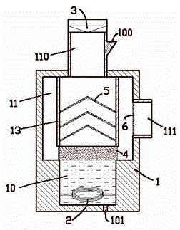
[0013] exist figure 1 In the shown embodiment one, the bionic air cleaner includes a base shell 1, a water storage chamber 10 is provided at the bottom of the base housing 1, and an electric heating tube 2 is arranged in it; above the water storage chamber 10 is An atomization chamber 11; above the atomization chamber 11 is an air inlet 110 equipped with an air intake fan 3; the side of the atomization chamber 11 is provided with an air outlet 111; The water inlet 100 and the water outlet 101 of the water storage chamber 10 are described; in the first embodiment, the water inlet 100 is arranged on the side of the air inlet 110, which is funnel-shaped to facilitate water intake; the water outlet 101 is arranged in the storage Water cavity 10 bottoms are equipped with drain switchgear, and also can be equipped with drainpipes.
[0014] In addition, in the first embodiment, the atomization chamber 11 is provided with a restriction tube 13 extending downward from the air inlet 11...
Embodiment 2
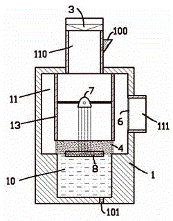
[0018] for figure 2 The second embodiment shown is different from the first embodiment in that there is a water tank 8 made of thermal insulation material floating in the water storage chamber 10; the upper bottom of the water tank 8 is provided with fine holes, and the water storage chamber 10 The water inside passes through the pores to form a thin water layer in the water tank 8; an infrared heating lamp 7 is set up above the water storage chamber 10, and the infrared heating lamp 7 faces the water tank 8; 8 is made of thermal insulation material, and the water body in the pores is thinner, basically has no convection function, and has poor thermal conductivity, so that in the water storage cavity 10, there is always only a thin water layer in the water tank 8 Heated, so that the water body in the water tank 8 can boil rapidly and generate a large amount of steam, thereby reducing the waste of heat caused by heating the water body in the water storage chamber 10 as a whole...
PUM
 Abstract
Description
Claims
Application Information