Liquid-level electrostatic precipitator

A technology of electrostatic precipitator and electrostatic generator, which is applied in the direction of external electrostatic separator, electrostatic separation, electrode structure, etc., can solve the problems of complex adsorption electrode structure of electrostatic precipitator, affecting the continuous operation of the factory, inconvenient dust cleaning, etc. To achieve the effect of continuous factory operation, simple operation and efficient adsorption

Inactive Publication Date: 2016-05-18
马海霞
View PDF6 Cites 7 Cited by
  • Summary
  • Abstract
  • Description
  • Claims
  • Application Information

AI Technical Summary

Problems solved by technology

[0002] With the seriousness of industrial pollution, the air quality has gradually declined; various factories have begun to remove dust and purify the exhaust gas emitted; at present, the traditional industrial dust collectors include filter cartridge dust collectors and electrostatic precipitators; among them, electrostatic precipitators are famous for their durability. The advantages of high pressure and high temperature resistance are gradually promoted. It uses electrodes to polarize dust and absorb dust through an electric field, which can effectively remove dust of various sizes; however, as the thickness of dust adsorbed on the electrode increases, the dust capture ability of the electrode will decrease. Gradually decline, the dust removal effect will be significantly reduced, so the electrostatic precipitator needs regular maintenance, affecting the continuous operation of the factory; the adsorption electrode structure of the traditional electrostatic precipitator is complicated, which also brings great inconvenience to the dust cleaning work

Method used


Image

  • Liquid-level electrostatic precipitator
  • Liquid-level electrostatic precipitator

Examples


Embodiment

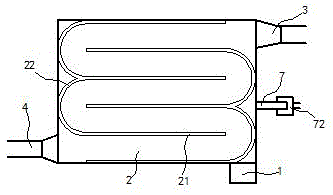
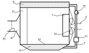
[0014] exist figure 1 , figure 2 In the shown embodiment, the liquid surface electrostatic precipitator includes an electrostatic generator 1, an air inlet 3, a dust removal chamber 2 and an exhaust port 4; a liquid storage chamber 5 is installed on the top of the dust removal chamber 2, and The liquid storage chamber 5 is filled with dust removal liquid; a dust collection chamber 6 is installed at the bottom of the dust removal chamber 2, and the dust collection chamber 6 and the dust removal chamber 2 are separated by a dust collection mesh plate 61; Dust removal plates 21 are arranged parallel and equidistant in the dust removal chamber 2, and each dust removal board 21 is vertically fixed in the dust removal chamber 2; each dust removal board 21 is connected by arc-shaped tiles 22 and assembled into a serpentine channel; dust removal The upper end of the plate 21 runs through the bottom of the liquid storage chamber 5 and extends into the dust removal liquid, and the low...


PUM


Abstract

The invention relates to a liquid-level electrostatic precipitator. The liquid-level electrostatic precipitator comprises an electrostatic generator, an air inlet, a dust removal cavity and an exhaust port, wherein a liquid storage cavity is mounted at the top of the dust removal cavity; a dust collection cavity is mounted at the bottom of the dust removal cavity; dust removal plates are distributed in the dust removal cavity in parallel at the equal interval; all the dust removal plates are connected by the aid of arc-shaped tiles and assembled to form an S-shaped channel; upper ends of the dust removal plates penetrate through the bottom of the liquid storage cavity and extend into a dust removal liquid, and lower ends of the dust removal plates are fixed on a dust collection screen; the dust collection cavity and the liquid storage cavity are connected by the aid of a flow guide pipe; a driver and a dust separator are sequentially connected onto the flow guide pipe in series; a discharge piece is mounted at the air inlet and electrically connected with one electrode of the electrostatic generator, and all the dust removal plates are electrically connected with the other electrode of the electrostatic generator. The precipitator is novel in structure and can work continuously for a long time, and the working efficiency is effectively improved; meanwhile, the dust removal work is simple and efficient.

Description

technical field [0001] The invention relates to a dust collector, in particular, an electrostatic dust collector. Background technique [0002] With the seriousness of industrial pollution, the air quality has gradually declined; various factories have begun to remove dust and purify the exhaust gas emitted; at present, the traditional industrial dust collectors include filter cartridge dust collectors and electrostatic precipitators; among them, electrostatic precipitators are famous for their durability. The advantages of high pressure and high temperature resistance are gradually promoted. It uses electrodes to polarize dust and absorb dust through an electric field, which can effectively remove dust of various sizes; however, as the thickness of dust adsorbed on the electrode increases, the dust capture ability of the electrode will decrease. Gradual decline, the dust removal effect will be significantly reduced, so the electrostatic precipitator needs regular maintena...

Claims


Application Information

Patent Timeline
Patent Type & Authority Applications(China)
IPC IPC(8): B03C3/16B03C3/53B03C3/34
CPCB03C3/16B03C3/34B03C3/53
Inventor 王富强
Owner 马海霞
Why Eureka
Try Eureka