Steel pipe bending machine

A technology of bending machine and steel pipe, applied in the field of steel pipe bending machine, can solve the problems of small feeding traction and easy slipping, and achieve the effect of increasing friction, increasing friction coefficient, and preventing slipping

Inactive Publication Date: 2016-05-18
ZHEJIANG HUXIN STAINLESS STEEL MFG
View PDF8 Cites 22 Cited by
  • Summary
  • Abstract
  • Description
  • Claims
  • Application Information

AI Technical Summary

Problems solved by technology

[0003] The invention provides a steel pipe bending machine with a large traction force during feeding, which solves the problem that the

Method used


Image

  • Steel pipe bending machine
  • Steel pipe bending machine
  • Steel pipe bending machine

Examples


Embodiment 1

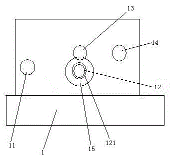
[0030] Embodiment one, see figure 1 , a steel pipe bending machine, including a frame 1. The frame 1 is provided with a bending roller 11, a driving roller 12, a second limiting roller 13, a first limiting roller 14 and a motor 15 for driving the driving roller. The surface of the driving roller 12 is provided with a resistance increasing layer 121 . The resistance-increasing layer 121 is composed of 20% steel particles and 80% rubber vulcanized together. The particle size of the steel shot is less than 1mm.

Embodiment 2

[0031] Embodiment two, the difference with embodiment one is:

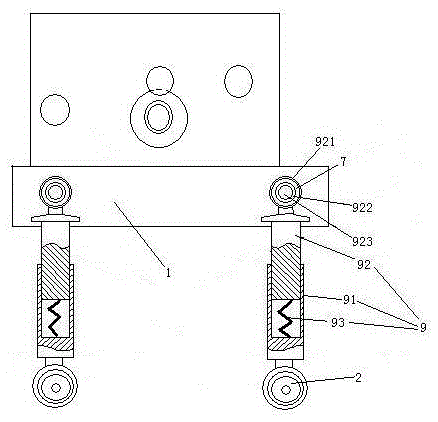
[0032] see figure 2 , Machine foot 1 is also provided with machine foot 9. The machine foot 9 includes a lower section 91 and an upper section 92 . The lower end of the lower section 91 is provided with a road wheel 2 . The upper end of the lower section 91 is slidably sleeved on the lower end of the upper section 92 . The lower section 81 is provided with a damping spring 93 supporting the upper section 92 . The upper end of the upper section 92 is provided with a connecting ring 921 . An inner ring 922 passes through the connecting ring 921 . The inner ring 922 is connected with the connecting ring 921 through the rubber ring 7 . The inner ring 922 is pierced with connecting pins 923 . The connecting pin 923 is connected with the frame 1 together.

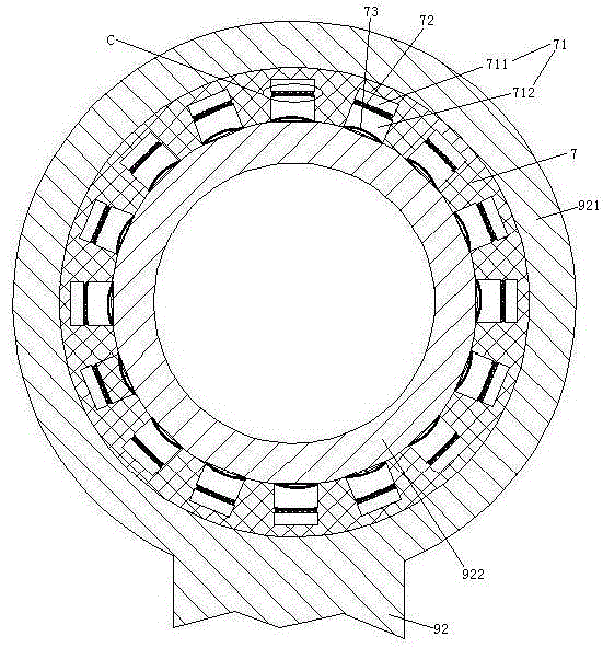
[0033] see image 3 , The inner peripheral surface of the rubber ring 7 is provided with several blind holes 71 distributed along the circumferential direc...

Embodiment 3

[0038] Embodiment three, the difference with embodiment two is:

[0039] see Figure 7 , the traveling wheel 2 comprises a spoke 222, a wheel rim 21 connected to the spoke, a pneumatic tire 23 connected to the wheel rim and an anti-puncture mechanism 29. The tire puncture prevention mechanism 29 includes a drum 291 , an air storage cylinder 292 , a threaded sleeve 293 , a screw mandrel 294 and a differential mechanism 295 . The rim 21 is provided with a pneumatic tire 23 . The roller 291 is coaxially fixed with the rim 21 . The roller 291 and the rim 21 are distributed along the axial direction of the rim 21 . The difference between the radius R1 of the tire minus the radius R2 of the drum is less than half the tire section height H and greater than 1 cm. The drum 291 is provided with an anti-rotation structure 2911 . The anti-rotation structure 2911 is a long hole disposed on the roller 291 and extending in the axial direction of the rim. The air storage cylinder 292 is...


PUM

PropertyMeasurementUnit
Graininessaaaaaaaaaa

Abstract

The invention relates to a steel pipe processing device. A steel pipe bending machine comprises a frame, wherein a bending roller, a driving roller, a limiting roller and a motor for driving the driving roller are arranged on the frame; a resistance increasing layer is arranged on the surface of the driving roller; the resistance increasing layer is formed by vulcanizing 20% of steel particles and 80% of rubber together; the particle size of the steel particles is smaller than 1mm. The steel pipe bending machine is high in traction force during feeding; the problem of low traction force caused by high possibility of slippage of the driving wheel of the steel pipe bending machine in the prior art during driving can be solved.

Description

technical field [0001] The invention relates to steel pipe processing equipment, in particular to a steel pipe bending machine. Background technique [0002] Steel pipe bending is done by steel pipe bending machine. A kind of existing steel pipe bending machine is disclosed in the patent document with the Chinese patent number 2015202742010, the announcement number CN204657186U, the publication date being September 23, 2015, and the title "a steel pipe bending machine". The basic structure of the steel pipe bending machine includes a frame, and the frame is equipped with bending rollers, driving rollers, limit rollers and motors that drive the driving rollers. The existing steel pipe bending machine has the following disadvantages: the frictional force of the driving wheel is small when driving, and slipping is easy to occur; the shock isolation effect is poor; and it is inconvenient to move. Contents of the invention [0003] The invention provides a steel pipe bending ...

Claims


Application Information

Patent Timeline
IPC IPC(8): B21D7/08B21D7/16
CPCB21D7/08B21D7/16
Inventor 郑祥清郑慧倩
Owner ZHEJIANG HUXIN STAINLESS STEEL MFG
Why Eureka
Try Eureka